
Page 563 - 2019 SHOP MANUAL CRF1000/A/D
P. 563
dummyheadmmyhead
du
IMMOBILIZER SYSTEM (HISS)
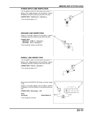
POWER INPUT LINE INSPECTION
Turn the ignition switch ON and engine stop switch " ".
[1]
Measure the voltage between the immobilizer receiver
4P (Black) connector [1] and ground at the wire side.
CONNECTION: Yellow/red (+) – Ground (–)
There should be approx. 5 V.
Y/R
GROUND LINE INSPECTION
Check for continuity between the immobilizer receiver
4P (Black) connector [1] and ground at the wire side. [1]
CONNECTION:
CRF1000/A: Gr/Bl (+) – Ground (–)
CRF1000D: Gr (+) – Ground (–)
Gr/Bl or Gr
There should be continuity at all times.
SIGNAL LINE INSPECTION
Turn the ignition switch ON and engine stop switch " ".
[1]
Measure the voltage between the immobilizer receiver
4P (Black) connector [1] and ground at the wire side.
CONNECTION: Pink (+) – Ground (–)
There should be approx. 5 V.
P
Disconnect the ECM/PCM 33P (Gray) connector (page
4-39). [1] [2]
Check for continuity between the immobilizer receiver
4P (Black) [1] and 33P (Gray) [2] connectors at the wire
side.
CONNECTION: Blue/orange – C21
TOOL:
Test probe 07ZAJ-RDJA110 Bu/O C21
There should be continuity.
23-11