Page 555 - 2019 SHOP MANUAL CRF1000/A/D
P. 555

dummyheadmmyhead
             du

                                                                                    IMMOBILIZER SYSTEM (HISS)
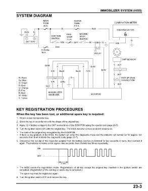
               SYSTEM DIAGRAM

                                     MAIN                     CLOCK
                                     FUSE                     TURN                              COMBINATION METER
                                     30 A                     7.5 A
                                                    R                        R/W                  HISS INDICATOR
                     Bl/Gr   Bl
                                                        ENG        ENGINE
                                            IGNITION    STOP       STOP
                                            SWITCH      7.5 A      SWITCH
                      BATTERY                      R/Bl       W/Y          Bl        G           R/Bl        G

                                               R/W
                                   FI FUSE                                     FI
                                   15 A                                        RELAY

                                                                                                      CKP SENSOR

                                      Gr/Bl     P                    P      Gr/Bl              Y  W/Y

                                                                                     Bl/W
                                           Y/R    Bu/O          Bu/O    Y/R
                                                                                               Y  W/Y
                Bl: Black                                  G                                         HISS 2P (Red)
                Bu: Blue                                                                             CONNECTOR
                G: Green                   Y/R     O/Bu                                           W/Y
                R: Red                 G/O      P                                              Y
                O: Orange
                P: Pink
                R: Red                   IMMOBILIZER                        ECM/PCM
                W: White                 RECEIVER
                Y: Yellow


               KEY REGISTRATION PROCEDURES
               When the key has been lost, or additional spare key is required:
               1. Obtain a new transponder key.
               2. Grind the key in accordance with the shape of the original key.
               3. Apply 12 V battery voltage to the CKP sensor lines of the ECM/PCM using the special tool (page 23-7).
               4. Turn the ignition switch ON with the original key. The HISS indicator comes on and it remains on.
                • The code of the original key recognized by the ECM/PCM.
                • If there is any problem in the HISS, the system will enter the diagnostic mode and the indicator will remain on for approx. ten
                 seconds, then it will indicate the diagnostic code (page 23-7).
               5. Disconnect the red clip of the inspection adaptor from the battery positive (+) terminal for two seconds or more, then connect it
                 again. The indicator remains on for approx. two seconds, then it blinks four times repeatedly.
                                ON


                                OFF


                                                   2 sec.
                • The HISS enters the  registration mode. Registrations of all key except the original  key  inserted in  the ignition switch are
                 cancelled. (Registration of the lost key or spare key is cancelled.)
                 The spare key must be registered again.
               6. Turn the ignition switch OFF and remove the key.


                                                                                                               23-3
   550   551   552   553   554   555   556   557   558   559   560