Page 551 - 2019 SHOP MANUAL CRF1000/A/D
P. 551

dummyheadmmyhead
             du

                                                                                      LIGHTS/METERS/SWITCHES
                               REAR ABS SWITCH INSPECTION
                               Remove the right middle cowl (page 2-6).
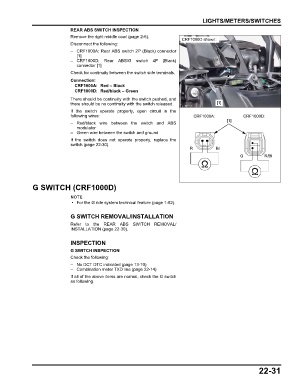
                                                                             CRF1000D shown:
                               Disconnect the following:
                               – CRF1000A: Rear ABS switch 2P (Black) connector
                                 [1]
                               – CRF1000D: Rear  ABS/G switch 4P  (Black)
                                 connector [1]
                               Check for continuity between the switch side terminals.
                               Connection:
                                CRF1000A: Red – Black
                                CRF1000D: Red/black – Green
                               There should be continuity with the switch pushed, and
                               there should be no continuity with the switch released.      [1]
                               If the switch operate properly, open circuit in the
                               following wires:                                   CRF1000A:            CRF1000D:
                                                                                                [1]
                               – Red/black wire between the switch and ABS
                                 modulator
                               – Green wire between the switch and ground
                               If the switch does not operate properly, replace the
                               switch (page 22-30).
                                                                                R          Bl
                                                                                                     G          R/Bl


               G SWITCH (CRF1000D)


                                • For the G ride system technical feature (page 1-52).


                               G SWITCH REMOVAL/INSTALLATION
                               Refer to the REAR ABS  SWITCH REMOVAL/
                               INSTALLATION (page 22-30).

                               INSPECTION

                               G SWITCH INSPECTION
                               Check the following:
                               – No DCT DTC indicated (page 13-10)
                               – Combination meter TXD line (page 22-14)
                               If all of the above items are normal, check the G switch
                               as following.


                                                                                                             22-31
   546   547   548   549   550   551   552   553   554   555   556