
Page 546 - 2019 SHOP MANUAL CRF1000/A/D
P. 546
du
dummyheadmmyhead
LIGHTS/METERS/SWITCHES
SYSTEM INSPECTION
If the gear position switch indicator does not operate
properly, check the combination meter initial operation [1]
(page 22-12).
If the combination meter system inspection is OK,
check the gear position switch line as follows:
Disconnect the combination meter 32P (Gray)
connector (page 22-12)
Check for continuity between the wire harness side 32P
(Gray) connector [1] and ground.
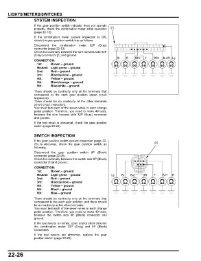
Br R Bl/Y Y Bl/O Bu/W Lg
CONNECTION:
1st: Brown – ground
Neutral: Light green – ground
2nd: Red – ground
3rd: Black/yellow – ground
4th: Yellow – ground
5th: Black/orange – ground
6th: Blue/white – ground
There should be continuity only at the terminals that
correspond to the each gear position (open circuit
inspection).
There should be no continuity at the other terminals
(short circuit inspection).
You must test each of the seven wires in each change
pedal position. Therefore, you need to make 49 tests,
between the wire harness side 32P (Gray) connector
and ground.
If the test result is abnormal, check the gear position
switch (page 22-26).
SWITCH INSPECTION
If the gear position switch system inspection (page 22-
26) is abnormal, check the gear position switch as [1]
following.
Disconnect the gear position switch 8P (Black)
connector (page 22-25).
Check for continuity between the switch side 8P (Black)
connector [1] and ground.
CONNECTION:
1st: Brown – ground
Neutral: Light green – ground Lg Br Bu Bl Y Bl/Y R
2nd: Red – ground
3rd: Black/yellow – ground
4th: Yellow – ground
5th: Black – ground
6th: Blue – ground
There should be continuity only at the terminals that
correspond to the each gear position, and there should
be no continuity at the other terminals.
You must test each of the seven wires in each change
pedal position. Therefore, you need to make 49 tests,
between the switch side 8P (Black) connector and
ground.
If the test results is normal, open and/or short circuit in
the combination meter 32P (Gray) and 8P (Black)
connectors.
If the test results are abnormal, replace the gear
position switch (page 22-25).
22-26