
Page 541 - 2019 SHOP MANUAL CRF1000/A/D
P. 541
dummyheadmmyhead
du
LIGHTS/METERS/SWITCHES
Installation is in the reverse order of removal.
TORQUE:
EOP sensor:
22 N·m (2.2 kgf·m, 16 lbf·ft)
• Replace the O-ring with a new one.
• Apply engine oil to the O-ring [1].
• Route the wire properly (page 1-26). [1]
Fill the engine oil with the recommended engine oil
(page 3-12).
FUEL LEVEL SENSOR/FUEL RESERVE
SENSOR
SYSTEM INSPECTION
The fuel meter indicates the warning display.
When an open or short circuit occur in the fuel meter
system, the fuel gauge indicators will be displayed as
shown with the ignition switch turned ON.
Check the following:
– Red/black wire between the fuel reserve sensor and
combination meter for open or short circuit
– Green wire between the fuel reserve sensor and
ground for open circuit
– Red/black wire between the fuel level sensor and
combination meter for open or short circuit
– Green wire between the fuel level sensor and
ground for open circuit
If they are normal, inspect the fuel level sensor (page
22-21)
If the fuel level sensor is normal, replace the fuel pump
unit with a new one and recheck (page 7-7).
Fuel meter does not operate properly.
• Check the initial function of the combination meter.
(page 22-12).
Inspect the fuel level sensor (page 22-21)
If the fuel level sensor is normal, replace the
combination meter (page 22-12) and recheck.
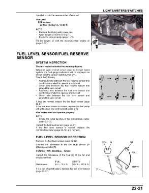
FUEL LEVEL SENSOR INSPECTION
Remove the fuel level sensor (page 22-22).
R/Bu G [2]
Connect the ohmmeter to the fuel level sensor 2P
(Black) connector [1].
CONNECTION: Red/blue – Green
FULL
Inspect the resistance of the float [2] at the full and
empty positions.
FULL EMPTY
Resistance 6.4 – 10.4 Ω 204.8 – 210.8 Ω
EMPTY
If it is out of specification, replace the fuel level sensor [1]
(page 22-22).
22-21