Page 544 - 2019 SHOP MANUAL CRF1000/A/D
P. 544

du
             dummyheadmmyhead

      LIGHTS/METERS/SWITCHES
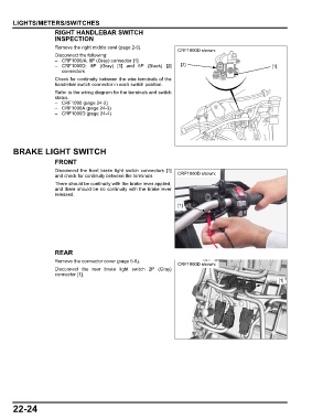
                      RIGHT HANDLEBAR SWITCH
                      INSPECTION
                      Remove the right middle cowl (page 2-6).
                                                                    CRF1000D shown:
                      Disconnect the following:
                      – CRF1000/A: 8P (Gray) connector [1]
                      – CRF1000D: 8P (Gray)  [1]  and 6P  (Black) [2]  [2]                              [1]
                        connectors
                      Check for continuity between the wire terminals of the
                      handlebar switch connector in each switch position.
                      Refer to the wiring diagram for the terminals and switch
                      status.
                      – CRF1000 (page 24-2)
                      – CRF1000A (page 24-3)
                      – CRF1000D (page 24-4)


      BRAKE LIGHT SWITCH

                      FRONT
                      Disconnect  the  front brake light switch connectors [1]
                      and check for continuity between the terminals.  CRF1000D shown:
                      There should be continuity with the brake lever applied,
                      and there should be no continuity with the brake lever
                      released.

                                                                    [1]


                      REAR
                      Remove the connector cover (page 5-8).
                                                                    CRF1000D shown:
                      Disconnect the rear brake light switch 2P (Gray)
                      connector [1].
                                                                                                           [1]


      22-24
   539   540   541   542   543   544   545   546   547   548   549