
Page 542 - 2019 SHOP MANUAL CRF1000/A/D
P. 542
dummyheadmmyhead
du
LIGHTS/METERS/SWITCHES
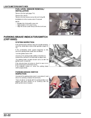
FUEL LEVEL SENSOR REMOVAL/
INSTALLATION
Remove the fuel tank (page 7-6).
[1]
Remove the nuts [1].
Remove the fuel reserve sensor [2] and O-ring [3].
Installation is in the reverse order of removal.
[2]
• Replace the O-ring with a new one.
• Apply engine oil to a new O-ring.
• Align the sensor plate hole [4] with the tank boss.
[4] [3]
PARKING BRAKE INDICATOR/SWITCH
(CRF1000D)
SYSTEM INSPECTION
If the parking brake indicator does not operate properly,
check the combination meter initial operation (page 22-
12).
If the combination meter system inspection is OK,
check the parking brake switch line as follows:
Turn the ignition switch OFF.
Disconnect the parking brake switch connectors [1].
Connect the connector terminals with a jumper wire.
The parking brake indicator should come on with the
ignition switch turned ON.
If the indicator does not come on, check for open circuit
in the Green/yellow and Green wires. [1]
If the indicator comes on, check the parking brake
switch (page 22-22).
PARKING BRAKE SWITCH
INSPECTION
Disconnect the parking brake switch connectors [1] and
check for continuity between the terminals.
There should be continuity with the parking brake lever
applied, and there should be no continuity with the
parking brake lever released.
[1]
22-22