
Page 543 - 2019 SHOP MANUAL CRF1000/A/D
P. 543
dummyheadmmyhead
du
LIGHTS/METERS/SWITCHES
IGNITION SWITCH
INSPECTION
Remove the fuel tank (page 7-6).
Disconnect the ignition switch 2P (Brown) connector [1].
Check for continuity between the wire terminals of the
ignition switch connector in each switch position.
Refer to the wiring diagram for the terminals and switch
status.
– CRF1000 (page 24-2)
– CRF1000A (page 24-3)
– CRF1000D (page 24-4)
[1]
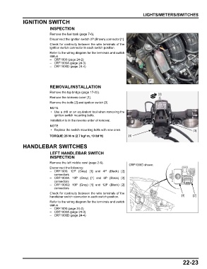
REMOVAL/INSTALLATION
Remove the top bridge (page 17-22).
[2]
Remove the harness cover [1].
Remove the bolts [2] and ignition switch [3].
• Use a drill or an equivalent tool when removing the
ignition switch mounting bolts.
Installation is in the reverse order of removal.
• Replace the switch mounting bolts with new ones. [3]
TORQUE:26 N·m (2.7 kgf·m, 19 lbf·ft) [1]
HANDLEBAR SWITCHES
LEFT HANDLEBAR SWITCH
INSPECTION
Remove the left middle cowl (page 2-6).
CRF1000D shown:
Disconnect the following:
– CRF1000: 12P (Gray) [1] and 4P (Black) [2]
connectors
– CRF1000A: 10P (Gray) [1] and 6P (Black) [2]
connectors
– CRF1000D: 10P (Gray) [1] and 12P (Black) [2]
connectors
Check for continuity between the wire terminals of the
handlebar switch connector in each switch position. [1] [2]
Refer to the wiring diagram for the terminals and switch
status.
– CRF1000 (page 24-2)
– CRF1000A (page 24-3)
– CRF1000D (page 24-4)
22-23