
Page 536 - 2019 SHOP MANUAL CRF1000/A/D
P. 536
du
dummyheadmmyhead
LIGHTS/METERS/SWITCHES
SPEEDOMETER/VS SENSOR
SYSTEM INSPECTION
If the speedometer does not operate, check the
following:
– Combination meter initial operation (page 22-12)
– MIL blinking: If the MIL blinks 11 (DTC 11-1), check
the VS sensor system (page 4-21)
If the above items are OK, open circuit in the Pink wire.
VS SENSOR REMOVAL/
INSTALLATION
Remove the battery box (page 21-6).
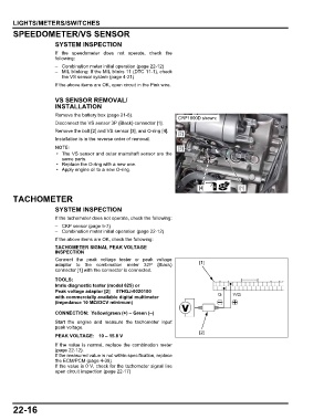
CRF1000D shown:
Disconnect the VS sensor 3P (Black) connector [1].
Remove the bolt [2] and VS sensor [3], and O-ring [4].
[2]
Installation is in the reverse order of removal.
[3]
• The VS sensor and outer mainshaft sensor are the
same parts.
• Replace the O-ring with a new one.
• Apply engine oil to a new O-ring.
[4] [1]
TACHOMETER
SYSTEM INSPECTION
If the tachometer does not operate, check the following:
– CKP sensor (page 5-7)
– Combination meter initial operation (page 22-12)
If the above items are OK, check the following:
TACHOMETER SIGNAL PEAK VOLTAGE
INSPECTION
Connect the peak voltage tester or peak voltage
adaptor to the combination meter 32P (Black) [1]
connector [1] with the connector is connected.
TOOLS:
Imrie diagnostic tester (model 625) or
Peak voltage adaptor [2] 07HGJ-0020100
with commercially available digital multimeter G Y/G
(impedance 10 MΩ/DCV minimum)
CONNECTION: Yellow/green (+) – Green (–)
Start the engine and measure the tachometer input
peak voltage.
[2]
PEAK VOLTAGE: 10 – 15.8 V
If the value is normal, replace the combination meter
(page 22-12).
If the measured value is not within specification, replace
the ECM/PCM (page 4-39).
If the value is 0 V, check for the tachometer signal line
open circuit inspection (page 22-17)
22-16