
Page 533 - 2019 SHOP MANUAL CRF1000/A/D
P. 533
dummyheadmmyhead
du
LIGHTS/METERS/SWITCHES
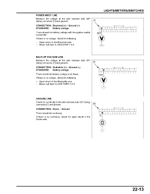
POWER INPUT LINE
Measure the voltage at the wire harness side 32P
(Gray) connector [1] and ground. [1]
CONNECTION: Black/red (+) – Ground (–)
STANDARD: Battery voltage
There should be battery voltage with the ignition switch Bl/R
turned ON.
If there is no voltage, check the following:
– Open circuit in the Black/red wire
– Blown sub fuse ILLUMI STOP 7.5 A
BACK-UP VOLTAGE LINE
Measure the voltage at the wire harness side 32P
(Gray) connector [1] and ground. [1]
CONNECTION: Red/white (+) – Ground (–)
STANDARD: Battery voltage
There should be battery voltage at all times. R/W
If there is no voltage, check the following:
– Open circuit in the Red/white wire
– Blown sub fuse CLOCK TURN 7.5 A
GROUND LINE
Check for continuity at the wire harness side 32P (Gray)
connector [1] and ground. [1]
CONNECTION: Green – Ground
There should be continuity.
G
If there is no continuity, check for open circuit in the
Green wire.
22-13