
Page 532 - 2019 SHOP MANUAL CRF1000/A/D
P. 532
dummyheadmmyhead
du
LIGHTS/METERS/SWITCHES
COMBINATION METER
REMOVAL/INSTALLATION
Remove the inner panel cover (page 2-8).
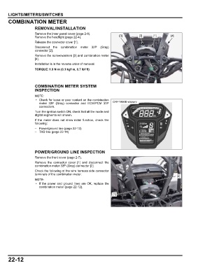
Remove the headlight (page 22-4). [3] [2] [1] [4]
Release the connector cover [1].
Disconnect the combination meter 32P (Gray)
connector [2].
Remove the screw/washers [3] and combination meter
[4].
Installation is in the reverse order of removal.
TORQUE:1.0 N·m (0.1 kgf·m, 0.7 lbf·ft)
COMBINATION METER SYSTEM
INSPECTION
• Check for loose or poor contact on the combination
meter 32P (Gray) connector and ECM/PCM 33P CRF1000D shown:
connectors.
Turn the ignition switch ON, check that all the mode and
digital segments will shown.
If the meter does not show initial function, check the
following:
– Power/ground line (page 22-12)
– TXD line (page 22-14)
POWER/GROUND LINE INSPECTION
Remove the front cover (page 2-7).
Remove the connector cover [1] and disconnect the
combination meter 32P (Gray) connector [2].
Check the following at the wire harness side connector
terminals of the combination meter.
[2]
• If the power and ground lines are OK, replace the
combination meter (page 22-12).
[1]
22-12