
Page 110 - 2019 SHOP MANUAL CRF1000/A/D
P. 110
du
dummyheadmmyhead
PGM-FI SYSTEM
SERVICE INFORMATION
PGM-FI SYSTEM
GENERAL
• This section covers electrical system service of the PGM-FI system. For other service and fuel supply system, see Fuel System
section (page 7-2)
• A faulty PGM-FI system is often related to poorly connected or corroded connectors. Check those connections before
proceeding.
• The PGM-FI system is equipped with the Self-Diagnostic System (page 4-5). If the MIL blinks, follow the Self-Diagnostic
Procedures to remedy the problem.
• When checking the PGM-FI, always follow the steps in the troubleshooting flow chart.
• If the ECM/PCM is replaced, perform the following procedure.
– Key Registration Procedure (page 23-3)
– Clutch Initialize Learning Procedure (CRF1000D) (page 13-82)
• The PGM-FI system is provided with fail-safe function to secure a minimum running capability even when there is any trouble in
the system. When any abnormality is detected by the self-diagnosis function, running capability is secured by making use of the
numerical values of a situation preset in the simulated program map.
It must be remembered, however, that when any abnormality is detected in an injector, the fail-safe function stops the engine to
protect it from damage.
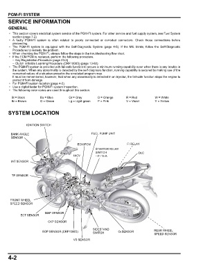
• For PGM-FI system location (page 4-2).
• Use a digital tester for PGM-FI system inspection.
• The following color codes are used throughout this section.
Bl = Black Bu = Blue Gr = Gray O = Orange R = Red W = White
Br = Brown G = Green Lg = Light green P = Pink V = Violet Y = Yellow
SYSTEM LOCATION
IGNITION SWITCH
BANK ANGLE FUEL PUMP UNIT
SENSOR
ECM/PCM FI RELAY
STARTER RELAY
SWITCH DLC
IACV – FI 15 A
IAT SENSOR
TP SENSOR
FRONT WHEEL
SPEED SENSOR
MAP SENSOR
ECT SENSOR
CKP SENSOR
SIDESTAND
EOP SENSOR (CRF1000D) SWITCH O2 SENSOR REAR WHEEL
SPEED SENSOR
VS SENSOR
4-2