
Page 115 - 2019 SHOP MANUAL CRF1000/A/D
P. 115
dummyheadmmyhead
du
PGM-FI SYSTEM
How to clear the DTC with SCS connector
1. Connect the SCS connector to the DLC (page 4-6).
2. Turn the ignition switch ON and engine stop switch " ".
3. Disconnect the SCS connector [1] from the DLC [2].
Connect the SCS connector to the DLC again while the MIL stays ON
about 5 seconds (reset receiving pattern). [1]
4. The stored DTC is erased if the MIL goes off and starts blinking
(successful pattern).
• The DLC must be jumped while the MIL lights. If not, the MIL will not
start blinking. In that case, turn the ignition switch OFF and try again
from step 3.
• Note that the self-diagnostic memory cannot be erased if the ignition
switch is turned OFF before the MIL starts blinking. [2]
CIRCUIT INSPECTION
• Always clean around and keep any foreign material away from the ECM/
PCM 33P connector before disconnecting it.
• A faulty PGM-FI system is often related to poorly connected or corroded
terminals. Check those connections before proceeding.
• In testing at ECM/PCM 33P connector (wire harness side) terminal,
always use the test probe [1]. Insert the test probe into the connector
terminal, then attach the digital multimeter probe to the test probe.
TOOL:
Test probe 07ZAJ-RDJA110
[1]
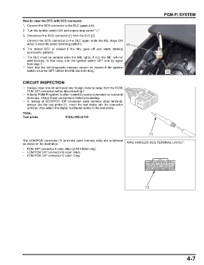
The ECM/PCM connector [1] terminals (wire harness side) are numbered
as shown in the illustration. WIRE HARNESS SIDE TERMINAL LAYOUT:
– PCM 33P connector A color: Blue (CRF1000D only)
– ECM/PCM 33P connector B color: Black
– ECM/PCM 33P connector C color: Gray
[1]
4-7