
Page 119 - 2019 SHOP MANUAL CRF1000/A/D
P. 119
dummyheadmmyhead
du
PGM-FI SYSTEM
DTC TROUBLESHOOTING
• If the ECM/PCM is replaced, perform the Key
Registration Procedure (page 23-3).
• CRF1000D: If the PCM is replaced, perform the
Clutch Initialize Learning Procedure (page 13-82).
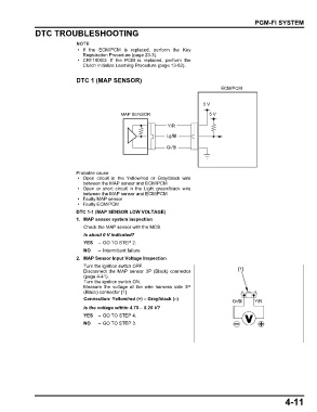
DTC 1 (MAP SENSOR)
ECM/PCM
5 V
MAP SENSOR 5 V
Y/R
Lg/Bl
Gr/Bl
Probable cause
• Open circuit in the Yellow/red or Gray/black wire
between the MAP sensor and ECM/PCM
• Open or short circuit in the Light green/black wire
between the MAP sensor and ECM/PCM
• Faulty MAP sensor
• Faulty ECM/PCM
DTC 1-1 (MAP SENSOR LOW VOLTAGE)
1. MAP sensor system inspection
Check the MAP sensor with the MCS.
Is about 0 V indicated?
YES – GO TO STEP 2.
NO – Intermittent failure
2. MAP Sensor Input Voltage Inspection
Turn the ignition switch OFF.
Disconnect the MAP sensor 3P (Black) connector [1]
(page 4-41).
Turn the ignition switch ON.
Measure the voltage at the wire harness side 3P
(Black) connector [1].
Connection: Yellow/red (+) – Gray/black (–) Gr/Bl Y/R
Is the voltage within 4.75 – 5.25 V?
YES – GO TO STEP 4.
NO – GO TO STEP 3.
4-11