Page 139 - 2019 SHOP MANUAL CRF1000/A/D
P. 139

dummyheadmmyhead
             du

                                                                                                   PGM-FI SYSTEM
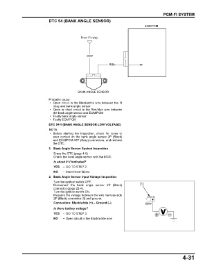
                               DTC 54 (BANK ANGLE SENSOR)
                                                                                        ECM/PCM


                                                  From FI relay


                                                     Bl/W


                                                                   R/Bu


                                                BANK ANGLE SENSOR

                               Probable cause
                                • Open circuit in the Black/white wire between the FI
                                 relay and bank angle sensor
                                • Open or short circuit in the Red/blue wire between
                                 the bank angle sensor and ECM/PCM
                                • Faulty bank angle sensor
                                • Faulty ECM/PCM
                               DTC 54-1 (BANK ANGLE SENSOR LOW VOLTAGE)

                                • Before starting the inspection, check for loose or
                                 poor contact on the bank  angle  sensor  2P  (Black)
                                 and ECM/PCM 33P (Gray) connectors, and recheck
                                 the DTC.
                               1. Bank Angle Sensor System Inspection
                                 Erase the DTC (page 4-6).
                                 Check the bank angle sensor with the MCS.
                                 Is about 0 V indicated?
                                 YES   – GO TO STEP 2.
                                 NO    – Intermittent failure
                               2. Bank Angle Sensor Input Voltage Inspection
                                 Turn the ignition switch OFF.
                                 Disconnect  the bank angle sensor 2P (Black)         [1]
                                 connector (page 22-4).
                                 Turn the ignition switch ON.
                                 Measure the voltage between the wire harness side
                                 2P (Black) connector [1] and ground.
                                 Connection: Black/white (+) – Ground (–)                Bl/W

                                 Is there battery voltage?
                                 YES   – GO TO STEP 3.
                                 NO    – Open circuit in the Black/white wire


                                                                                                               4-31
   134   135   136   137   138   139   140   141   142   143   144