
Page 142 - 2019 SHOP MANUAL CRF1000/A/D
P. 142
dummyheadmmyhead
du
PGM-FI SYSTEM
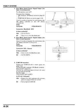
3. Rear Wheel Speed Sensor Signal Output Line
Open Circuit Inspection
Turn the ignition switch OFF.
[1] [2]
Disconnect the following:
– ABS modulator 18P (Black) connector (page 20-
7)
– ECM/PCM 33P (Black) connector (page 4-39)
Check for continuity between the wire harness side
18P (Black) connector [1] and 33P (Black)
connector [2].
TOOL: Bu/Bl B18
Test probe 07ZAJ-RDJA110
Connection: Blue/black – B18
Is there continuity?
YES – GO TO STEP 4.
NO – Open circuit in the Blue/black wire
4. Rear Wheel Speed Sensor Signal Output Line
Short Circuit Inspection
Check for continuity between the wire harness side
33P (Black) connector [1] and ground. [1]
TOOL:
Test probe 07ZAJ-RDJA110
Connection: B18 – Ground
Is there continuity?
YES – Short circuit in the Blue/black wire B18
NO – GO TO STEP 5.
5. ECM/PCM Inspection
Replace the ECM/PCM with a known good one
(page 4-39).
Connect the ABS modulator 18P (Black) connector.
Erase the DTC (page 4-6).
Test-ride the motorcycle above 20 km/h (12 mph)
for more than 20 seconds.
Stop the engine.
Check the DTC with the MCS.
Is DTC 66-1 indicated?
YES – Replace the ABS modulator with a known
good one (page 20-24) and recheck.
NO – Faulty original ECM/PCM
4-34