
Page 145 - 2019 SHOP MANUAL CRF1000/A/D
P. 145
dummyheadmmyhead
du
PGM-FI SYSTEM
2. EOP Sensor Inspection
Stop the engine.
Disconnect the EOP sensor 3P (Black) connector
(page 22-20).
Turn the ignition switch ON.
Check the EOP sensor with the MCS.
Is about 0 V indicated?
YES – GO TO STEP 3.
NO – Faulty EOP sensor
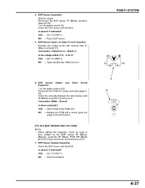
3. EOP Sensor Input Line Open Circuit Inspection
Measure the voltage at the wire harness side 3P
(Black) connector [1].
Connection: Yellow/red (+) – Black (–)
Is the voltage within 4.75 – 5.25 V?
YES – GO TO STEP 4.
NO – Open circuit in the Yellow/red wire Bl Y/R
[1]
4. EOP Sensor Output Line Short Circuit
Inspection
Turn the ignition switch OFF.
Disconnect the PCM 33P (Gray) connector (page 4- [1]
39).
Check for continuity between the wire harness side
3P (Black) connector [1] and ground.
Connection: White – Ground
Is there continuity? W
YES – Short circuit in the White wire
NO – Replace the PCM with a known good one
(page 4-39) and recheck.
DTC 83-2 (EOP SENSOR HIGH VOLTAGE)
• Before starting the inspection, check for loose or
poor contact on the EOP sensor 3P (Black),
alternator assembly 6P (Black), PCM 33P (Black)
and 33P (Gray) connectors, and recheck the DTC.
1. EOP Sensor System Inspection
Check the EOP sensor with the MCS.
Is about 5 V indicated?
YES – GO TO STEP 2.
NO – Intermittent failure
4-37