Page 148 - 2019 SHOP MANUAL CRF1000/A/D
P. 148

dummyheadmmyhead
             du

      PGM-FI SYSTEM
                      Disconnect the following:
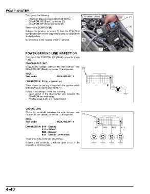
                                                                    CRF1000D shown:                        [1]
                      – PCM 33P (Blue) connector [1] (CRF1000D)
                      – ECM/PCM 33P (Black) connector [2]
                      – ECM/PCM 33P (Gray) connector [3]            [2]
                      Remove the ECM/PCM [4].                                                              [6]
                                                                    [3]
                      Release the junction terminals [5] from the ECM/PCM
                      stay [6] and remove the stay by releasing its tab [7] from
                      the battery box.
                      Installation is in the reverse order of removal.  [4]


                                                                                   [7]                     [5]
                      POWER/GROUND LINE INSPECTION

                      Disconnect the ECM/PCM 33P (Black) connector (page
                      4-39).
                      POWER INPUT LINE
                      Measure the  voltage between  the wire harness  side
                      ECM/PCM 33P (Black) connector [1] and ground.  [1]
                      TOOL:
                      Test probe               07ZAJ-RDJA110

                      CONNECTION: B1 (+) – Ground (–)
                      There should be battery voltage with the ignition switch          B1
                      turned ON and engine stop switch " ".
                      If there is no voltage, check the following:
                      – Open  circuit in the Black/white wire between the
                        ECM/PCM and main relay
                      – FI relay (page 4-43) and related circuit


                      GROUND LINE
                      Check for continuity between the  wire harness  side
                      ECM/PCM 33P (Black) connector [1] and ground.  [1]
                      TOOL:
                      Test probe               07ZAJ-RDJA110
                      CONNECTION: B11 – Ground                                B22     B33    B11    B12
                                   B12 – Ground
                                   B22 – Ground
                                   B33 – Ground (CRF1000D)
                      There should be continuity at all times.
                      If there is no continuity, check for open circuit in the
                      Green/blue or Green wire.


      4-40
   143   144   145   146   147   148   149   150   151   152   153