
Page 151 - 2019 SHOP MANUAL CRF1000/A/D
P. 151
dummyheadmmyhead
du
PGM-FI SYSTEM
Installation is in the reverse order of removal.
• Install the bank angle sensor with its "UP" mark [1]
facing up.
[1]
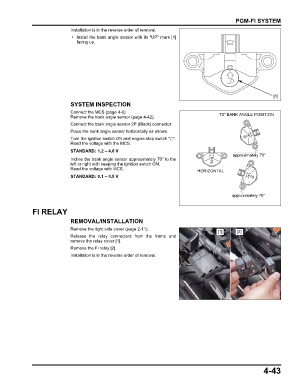
SYSTEM INSPECTION
Connect the MCS (page 4-6). 70° BANK ANGLE POSITION
Remove the bank angle sensor (page 4-42).
Connect the bank angle sensor 2P (Black) connector.
Place the bank angle sensor horizontally as shown.
Turn the ignition switch ON and engine stop switch " ".
Read the voltage with the MCS.
STANDARD: 1.2 – 4.6 V
approximately 70°
Incline the bank angle sensor approximately 70° to the
left or right with keeping the ignition switch ON.
Read the voltage with MCS. HORIZONTAL
STANDARD: 0.1 – 0.5 V
approximately 70°
FI RELAY
REMOVAL/INSTALLATION
Remove the right side cover (page 2-11).
[1] [2]
Release the relay connectors from the frame and
remove the relay cover [1].
Remove the FI relay [2].
Installation is in the reverse order of removal.
4-43