Page 146 - 2019 SHOP MANUAL CRF1000/A/D
P. 146

du
             dummyheadmmyhead

      PGM-FI SYSTEM
                      2. EOP Sensor Inspection
                         Turn the ignition switch OFF.
                         Disconnect the EOP sensor 3P (Black)  connector                   [1]
                         (page 22-20).
                         Connect the wire harness side 3P (Black) connector
                         [1] with a jumper wire [2].
                         Connection: White – Black
                         Turn the ignition switch ON.
                         Check the EOP sensor with the MCS.                        Bl    W
                         Is about 0 V indicated?
                         YES – Faulty EOP sensor
                         NO   – GO TO STEP 3.
                                                                                    [2]

                      3. EOP  Sensor Ground Line  Open Circuit
                         Inspection
                         Turn the ignition switch OFF.
                         Disconnect the PCM 33P (Black) connector (page       [1]           [2]
                         4-39).
                         Check for continuity between the wire harness side
                         sensor 3P (Black) connector [1] and  33P (Black)
                         connector [2].
                         TOOL:
                         Test probe            07ZAJ-RDJA110

                         Connection: Black – B13                          Bl                      B13
                         Is there continuity?
                         YES – GO TO STEP 4.
                         NO   – Open circuit in the Black  or  Gray/black
                                wire
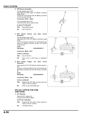
                      4. EOP   Sensor  Output  Line  Open   Circuit
                         Inspection
                         Disconnect the PCM 33P (Gray) connector (page 4-
                         39).                                                 [1]           [2]
                         Check for continuity between the wire harness side
                         3P (Black) connector [1] and 33P (Gray) connector
                         [2].
                         TOOL:
                         Test probe            07ZAJ-RDJA110
                         Connection: White – C26
                                                                             W                     C26
                         Is there continuity?
                         YES – Replace the PCM with a known good one
                                (page 4-39) and recheck.
                         NO   – Open circuit in the White wire


                      DTC 84-1 (CPU IN THE PCM)
                      (CRF1000D)
                      1. DTC Recheck
                         Erase the DTC (page 4-6).
                         Check the DTC with the MCS.
                         Is DTC 84-1 indicated?
                         YES  – Replace the PCM with a known good one
                                (page 4-39) and recheck.
                         NO   – Intermittent failure


      4-38
   141   142   143   144   145   146   147   148   149   150   151