
Page 140 - 2019 SHOP MANUAL CRF1000/A/D
P. 140
du
dummyheadmmyhead
PGM-FI SYSTEM
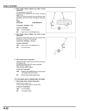
3. Bank Angle Sensor Signal Line Open Circuit
Inspection
Turn the ignition switch OFF.
Disconnect the ECM/PCM 33P (Gray) connector [1] [2]
(page 4-39).
Check for continuity between the wire harness side
2P (Black) connector [1] and 33P (Black) connector
[2].
TOOL:
Test probe 07ZAJ-RDJA110
Connection: Red/blue – C25 R/Bu C25
Is there continuity?
YES – GO TO STEP 4.
NO – Open circuit in the Red/blue wire
4. Bank Angle Sensor Signal Line Short Circuit
Inspection
Check for continuity between the wire harness side
2P (Black) connector [1] and ground. [1]
Connection: Red/blue – Ground
Is there continuity?
YES – Short circuit in the Red/blue wire
NO – GO TO STEP 5. R/Bu
5. Bank Angle Sensor Inspection
Replace the bank angle sensor with a known good
one (page 4-42).
Connect the ECM/PCM 33P (Gray) connector.
Erase the DTC (page 4-6).
Check the DTC with the MCS.
Is DTC 54-1 indicated?
YES – Replace the ECM/PCM with a known good
one (page 4-39) and recheck.
NO – Faulty original bank angle sensor
DTC 54-2 (BANK ANGLE SENSOR HIGH VOLTAGE)
1. Bank Angle Sensor System Inspection
Erase the DTC (page 4-6).
Check the bank angle sensor with the MCS.
Is about 5 V indicated?
YES – GO TO STEP 2.
NO – Intermittent failure
4-32