Page 191 - 2019 SHOP MANUAL CRF1000/A/D
P. 191

dummyheadmmyhead
             du

                                                                                                      FUEL SYSTEM
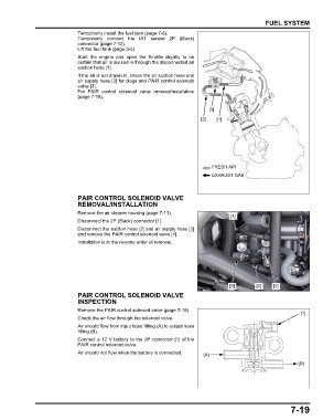
                               Temporarily install the fuel tank (page 7-6).
                               Temporarily connect the  IAT sensor 2P (Black)
                               connector (page 7-12).
                               Lift the fuel tank (page 3-3)
                               Start the engine and  open the  throttle slightly to  be
                               certain that air is sucked in through the disconnected air
                               suction hose [1].
                               If the air is not drawn in, check the air suction hose and
                               air supply hose [2] for clogs and PAIR control solenoid
                               valve [3].
                               For  PAIR  control solenoid valve removal/installation
                               (page 7-19).

                                                                                [3]

                                                                             [2]   [1]


                                                                                 FRESH AIR
                                                                                 EXHAUST GAS


                               PAIR CONTROL SOLENOID VALVE
                               REMOVAL/INSTALLATION

                               Remove the air cleaner housing (page 7-11).
                                                                                        [1]
                               Disconnect the 2P (Black) connector [1].
                               Disconnect the suction hose [2] and air supply hose [3]
                               and remove the PAIR control solenoid valve [4].
                               Installation is in the reverse order of removal.


                                                                                        [3]       [4]    [2]
                               PAIR CONTROL SOLENOID VALVE
                               INSPECTION
                               Remove the PAIR control solenoid valve (page 7-19).
                                                                                                                   [1]
                               Check the air flow through the solenoid valve.
                               Air should flow from input hose fitting (A) to output hose
                               fitting (B).
                               Connect a 12 V battery to the 2P connector [1] of the
                               PAIR control solenoid valve.
                               Air should not flow when the battery is connected.  (A)

                                                                                                                  (B)


                                                                                                               7-19
   186   187   188   189   190   191   192   193   194   195   196