
Page 126 - 2019 SHOP MANUAL CRF1000/A/D
P. 126
du
dummyheadmmyhead
PGM-FI SYSTEM
DTC 8-2 (TP SENSOR HIGH VOLTAGE)
1. TP Sensor System Inspection
Check the TP sensor with the MCS.
Is about 5 V indicated?
YES – GO TO STEP 2.
NO – GO TO STEP 3.
2. TP Sensor System Inspection with throttle
operated
Check that the TP sensor voltage increases
continuously when moving the throttle from fully
closed position to fully opened position using the
data list menu of the MCS.
Is the voltage increase continuously?
YES – Intermittent failure
NO – Faulty TP sensor (replace the throttle body
as assembly)
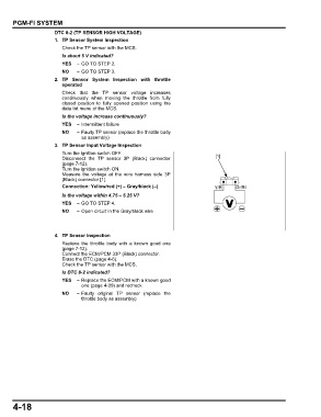
3. TP Sensor Input Voltage Inspection
Turn the ignition switch OFF.
Disconnect the TP sensor 3P (Black) connector [1]
(page 7-12).
Turn the ignition switch ON.
Measure the voltage at the wire harness side 3P
(Black) connector [1].
Connection: Yellow/red (+) – Gray/black (–) Y/R Gr/Bl
Is the voltage within 4.75 – 5.25 V?
YES – GO TO STEP 4.
NO – Open circuit in the Gray/black wire
4. TP Sensor Inspection
Replace the throttle body with a known good one
(page 7-12).
Connect the ECM/PCM 33P (Black) connector.
Erase the DTC (page 4-6).
Check the TP sensor with the MCS.
Is DTC 8-2 indicated?
YES – Replace the ECM/PCM with a known good
one (page 4-39) and recheck.
NO – Faulty original TP sensor (replace the
throttle body as assembly)
4-18