Page 130 - 2019 SHOP MANUAL CRF1000/A/D
P. 130

du
             dummyheadmmyhead

      PGM-FI SYSTEM
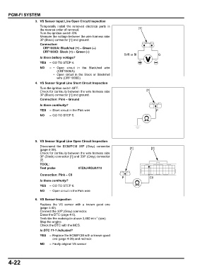
                      3. VS Sensor Input Line Open Circuit Inspection
                         Temporarily install the removed electrical parts in
                         the reverse order of removal.                             [1]
                         Turn the ignition switch ON.
                         Measure the voltage between the wire harness side
                         3P (Black) connector [1] and ground.
                         Connection:
                          CRF1000/A: Black/red (+) – Green (–)
                          CRF1000D: Black (+) – Green (–)
                                                                           Bl/R or Bl          G
                         Is there battery voltage?
                         YES  – GO TO STEP 4.
                         NO   –  • Open  circuit in the Black/red wire
                                   (CRF1000/A)
                                 • Open  circuit in the Black  or Black/red
                                   wire (CRF1000D)
                      4. VS Sensor Signal Line Short Circuit Inspection
                         Turn the ignition switch OFF.
                         Check for continuity between the wire harness side             [1]
                         3P (Black) connector [1] and ground.
                         Connection: Pink – Ground
                         Is there continuity?
                         YES  – Short circuit in the Pink wire                               P
                         NO   – GO TO STEP 5.


                      5. VS Sensor Signal Line Open Circuit Inspection
                         Disconnect the ECM/PCM 33P (Gray) connector
                         (page 4-39).                                         [1]         [2]
                         Check for continuity between the wire harness side
                         3P (Black) connector [1] and 33P (Gray) connector
                         [2].
                         TOOL:
                         Test probe            07ZAJ-RDJA110

                         Connection: Pink – C9
                                                                         P                C9
                         Is there continuity?
                         YES  – GO TO STEP 6.
                         NO   – Open circuit in the Pink wire

                      6. VS Sensor Inspection
                         Replace the  VS sensor  with a known  good one
                         (page 4-42).
                         Connect the 33P (Gray) connector.
                         Erase the DTC (page 4-6).
                         Test-ride the motorcycle above 3,400 min  (rpm).
                                                          -1
                         Stop the engine.
                         Check the DTC with the MCS.
                         Is DTC 11-1 indicated?
                         YES  – Replace the ECM/PCM with a known good
                                one (page 4-39) and recheck.
                         NO   – Faulty original VS sensor


      4-22
   125   126   127   128   129   130   131   132   133   134   135