
Page 231 - 2019 SHOP MANUAL CRF1000/A/D
P. 231
dummyheadmmyhead
du
CYLINDER HEAD/VALVE/CAMSHAFT
INSPECTION
Inspect the following parts for damage, abnormal wear,
deformation, burning or clogs in oil passages.
– Cylinder head
– Valve springs
– Valves
– Valve guides
Measure each part according to CYLINDER HEAD/
VALVE SPECIFICATIONS (page 1-7).
Replace any part if it is out of service limit.
• Ream the valve guide using the valve guide reamer
to remove any carbon build up before measuring the
guide (page 10-15).
• Refer to valve seat inspection (page 10-16).
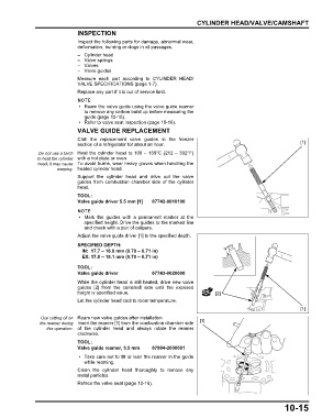
VALVE GUIDE REPLACEMENT
Chill the replacement valve guides in the freezer
section of a refrigerator for about an hour. [1]
Do not use a torch Heat the cylinder head to 100 – 150°C (212 – 302°F)
to heat the cylinder with a hot plate or oven.
head; it may cause To avoid burns, wear heavy gloves when handling the
warping. heated cylinder head.
Support the cylinder head and drive out the valve
guides from combustion chamber side of the cylinder
head.
TOOL:
Valve guide driver 5.5 mm [1] 07742-0010100
• Mark the guides with a permanent marker at the
specified height. Drive the guides to the marked line
and check with a pair of calipers.
Adjust the valve guide driver [1] to the specified depth.
SPECIFIED DEPTH:
IN: 17.7 – 18.0 mm (0.70 – 0.71 in)
EX: 17.8 – 18.1 mm (0.70 – 0.71 in)
TOOL:
Valve guide driver 07743-0020000
While the cylinder head is still heated, drive new valve
guides [2] from the camshaft side until the exposed
height is specified value. [2]
Let the cylinder head cool to room temperature.
[1]
Use cutting oil on Ream new valve guides after installation.
the reamer during Insert the reamer [1] from the combustion chamber side [1]
this operation. of the cylinder head and always rotate the reamer
clockwise.
TOOL:
Valve guide reamer, 5.5 mm 07984-2000001
• Take care not to tilt or lean the reamer in the guide
while reaming.
Clean the cylinder head thoroughly to remove any
metal particles.
Reface the valve seat (page 10-16).
10-15