Page 235 - 2019 SHOP MANUAL CRF1000/A/D
P. 235

dummyheadmmyhead
             du

                                                                            CYLINDER HEAD/VALVE/CAMSHAFT
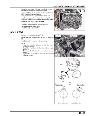
                               Route the cam chain [1] through the cylinder head and
                               install the cylinder head [2] onto the cylinder.         [2]               [3]
                               Apply molybdenum oil  solution to  the  cylinder head
                               bolts threads and seating surface.
                               Apply engine oil to the cylinder head bolt washers.
                               Install  and  tighten  the cylinder head bolts  [3] in a
                               crisscross pattern in 2 or 3 steps to the specified torque.
                               TORQUE:83 N·m (8.5 kgf·m, 61 lbf·ft)
                               Install and tighten the 6 mm bolts [4] securely.
                               Install the camshaft (page 10-9).             [4]
                               Install the engine (page 16-10).
                                                                                 [1]
               INSULATOR

                               Remove the throttle body (page 7-12).
                                                                             Left side:           Right side:
                               Loosen the band screws [1] and remove the insulators
                               [2].
                               Installation is in the reverse order of removal.


                                • Align the insulator  grooves [3]  with  the upper
                                 crankcase lugs [4].
                                • Install the insulators with the  stamped  mark  side
                                 facing up.
                                • Make sure that  the  band screws  is in  position as                             [1]
                                 shown.
                                • Tighten the insulator band screws to the specified
                                 range as shown.                             [1]  [2]                           [2]


                                                                                    [2]


                                                                                     [4]


                                                                                       [3]
                                                                                                Up
                                                                            12 ± 1.0 mm                    12 ± 1.0 mm
                                                                            (0.5 ± 0.04 in)                (0.5 ± 0.04 in)


                                                                             [1]                                    [1]


                                                                                 No.1 cylinder side:  No.2 cylinder side:


                                                                                                             10-19
   230   231   232   233   234   235   236   237   238   239   240