
Page 80 - 2019 SHOP MANUAL CRF1000/A/D
P. 80
du
dummyheadmmyhead
FRAME/BODY PANELS/EXHAUST SYSTEM
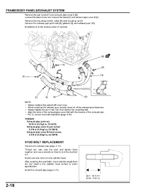
Remove the pan screw [1] and exhaust pipe cover A [2].
Loosen the band screw and remove the band [3] and exhaust pipe cover B [4].
Remove the mounting bolt [5], collar [6], and mounting nut [7].
Remove the exhaust pipe joint nuts [8], gaskets [9], and exhaust pipe [10].
Installation is in the reverse order of removal.
[9]
[6]
[7]
[8]
[10]
[5]
[1] [2] [4] [3]
• Always replace the gasket with new ones.
• When installing the exhaust pipe, loosely install all of the exhaust pipe fasteners.
• Always tighten the joint nuts first, then tighten the mounting bolt.
• Align the slots of the exhaust pipe cover A/B with the bosses of the exhaust pipe.
•For O2 sensor removal/installation (page 4-42)
TORQUE:
Exhaust pipe joint nut:
20 N·m (2.0 kgf·m, 15 lbf·ft)
Exhaust pipe cover A pan screw:
9.0 N·m (0.9 kgf·m, 6.6 lbf·ft)
Exhaust pipe cover B band screw:
3.5 N·m (0.4 kgf·m, 2.6 lbf·ft)
STUD BOLT REPLACEMENT
Remove the exhaust pipe (page 2-17).
Thread two nuts onto the stud and tighten them
together, and use a wrench on them to turn the stud bolt
out.
Install new stud bolts into the cylinder head.
After installing the stud bolts, check that the length from
the bolt head to the cylinder head surface is within
specification.
Install the exhaust pipe (page 2-17).
22.5 – 23.5 mm
(0.89 – 0.93 in)
2-18