
Page 160 - 2019 SHOP MANUAL CRF1000/A/D
P. 160
du
dummyheadmmyhead
IGNITION SYSTEM
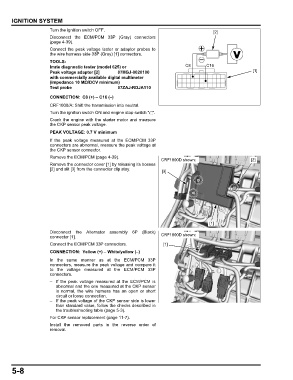
Turn the ignition switch OFF. [2]
Disconnect the ECM/PCM 33P (Gray) connectors
(page 4-39).
Connect the peak voltage tester or adaptor probes to
the wire harness side 33P (Gray) [1] connectors.
TOOLS:
Imrie diagnostic tester (model 625) or C8 C16
Peak voltage adaptor [2] 07HGJ-0020100 [1]
with commercially available digital multimeter
(impedance 10 MΩ/DCV minimum)
Test probe 07ZAJ-RDJA110
CONNECTION: C8 (+) – C16 (–)
CRF1000/A: Shift the transmission into neutral.
Turn the ignition switch ON and engine stop switch " ".
Crank the engine with the starter motor and measure
the CKP sensor peak voltage.
PEAK VOLTAGE: 0.7 V minimum
If the peak voltage measured at the ECM/PCM 33P
connectors are abnormal, measure the peak voltage at
the CKP sensor connector.
Remove the ECM/PCM (page 4-39).
CRF1000D shown: [2]
Remove the connector cover [1] by releasing its bosses
[2] and slit [3] from the connector clip stay. [3]
[1]
Disconnect the Alternator assembly 6P (Black)
connector [1]. CRF1000D shown:
Connect the ECM/PCM 33P connectors. [1]
CONNECTION: Yellow (+) – White/yellow (–)
In the same manner as at the ECM/PCM 33P
connectors, measure the peak voltage and compare it
to the voltage measured at the ECM/PCM 33P
connectors.
– If the peak voltage measured at the ECM/PCM is
abnormal and the one measured at the CKP sensor
is normal, the wire harness has an open or short
circuit or loose connection.
– If the peak voltage of the CKP sensor side is lower
than standard value, follow the checks described in
the troubleshooting table (page 5-3).
For CKP sensor replacement (page 11-7).
Install the removed parts in the reverse order of
removal.
5-8