
Page 20 - 2019 SHOP MANUAL CRF1000/A/D
P. 20
dummyheadmmyhead
du
GENERAL INFORMATION
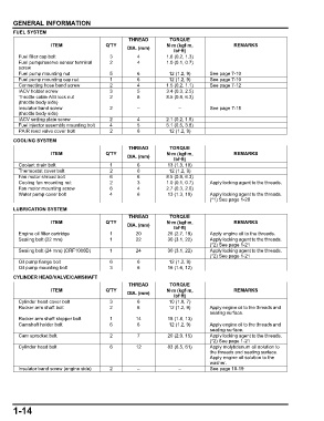
FUEL SYSTEM
THREAD TORQUE
ITEM Q'TY N·m (kgf·m, REMARKS
DIA. (mm)
lbf·ft)
Fuel filler cap bolt 3 4 1.8 (0.2, 1.3)
Fuel pump/reserve sensor terminal 2 4 1.0 (0.1, 0.7)
screw
Fuel pump mounting nut 5 6 12 (1.2, 9) See page 7-10
Fuel pump mounting cap nut 1 6 12 (1.2, 9) See page 7-10
Connecting hose band screw 2 4 1.5 (0.2, 1.1) See page 7-12
IACV holder screw 3 5 3.4 (0.3, 2.5)
Throttle cable A/B lock nut 2 8 8.5 (0.9, 6.3)
(throttle body side)
Insulator band screw 2 – – See page 7-15
(throttle body side)
IACV setting plate screw 2 4 2.1 (0.2, 1.5)
Fuel injector assembly mounting bolt 4 5 5.1 (0.5, 3.8)
PAIR reed valve cover bolt 2 6 12 (1.2, 9)
COOLING SYSTEM
THREAD TORQUE
ITEM Q'TY N·m (kgf·m, REMARKS
DIA. (mm)
lbf·ft)
Coolant drain bolt 1 6 13 (1.3, 10)
Thermostat cover bolt 2 6 12 (1.2, 9)
Fan motor shroud bolt 6 6 8.5 (0.9, 6.3)
Cooling fan mounting nut 2 3 1.0 (0.1, 0.7) Apply locking agent to the threads.
Fan motor mounting screw 6 4 2.7 (0.3, 2.0)
Water pump cover bolt 4 6 13 (1.3, 10) Apply locking agent to the threads.
(*1) See page 1-20
LUBRICATION SYSTEM
THREAD TORQUE
ITEM Q'TY N·m (kgf·m, REMARKS
DIA. (mm)
lbf·ft)
Engine oil filter cartridge 1 20 26 (2.7, 19) Apply engine oil to the threads.
Sealing bolt (22 mm) 1 22 30 (3.1, 22) Apply locking agent to the threads.
(*2) See page 1-21
Sealing bolt (24 mm) (CRF1000D) 1 24 30 (3.1, 22) Apply locking agent to the threads.
(*2) See page 1-21
Oil pump flange bolt 6 6 12 (1.2, 9)
Oil pump mounting bolt 3 6 16 (1.6, 12)
CYLINDER HEAD/VALVE/CAMSHAFT
THREAD TORQUE
ITEM Q'TY N·m (kgf·m, REMARKS
DIA. (mm)
lbf·ft)
Cylinder head cover bolt 3 6 10 (1.0, 7)
Rocker arm shaft bolt 2 6 12 (1.2, 9) Apply engine oil to the threads and
seating surface.
Rocker arm shaft stopper bolt 1 14 18 (1.8, 13)
Camshaft holder bolt 6 6 12 (1.2, 9) Apply engine oil to the threads and
seating surface.
Cam sprocket bolt 2 7 20 (2.0, 15) Apply locking agent to the threads.
(*2) See page 1-21
Cylinder head bolt 6 12 83 (8.5, 61) Apply molybdenum oil solution to
the threads and seating surface.
Apply engine oil solution to the
washer.
Insulator band screw (engine side) 2 – – See page 10-19
1-14