Page 445 - 2019 SHOP MANUAL CRF1000/A/D
P. 445

dummyheadmmyhead
             du

                                                                                      REAR WHEEL/SUSPENSION
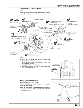
                               DISASSEMBLY/ASSEMBLY


                               Install the driven sprocket on the driven flange with the
                               stamped mark facing out.


                                                   DRIVEN FLANGE
                                  BEARING 63/22                           PULSER RING BOLTS         BRAKE DISC BOLTS
                DUST SEAL
                                                                          (CRF1000A/D)               42 N·m
                                                                          7.0 N·m (0.7 kgf·m, 5.2 lbf·ft)  (4.3 kgf·m, 31 lbf·ft)
                DRIVEN
                SPROCKET                                    REAR WHEEL
                                                            DISTANCE COLLAR B
                                                                  PULSER RING
                                                                  (CRF1000A/D)
                                                                                                      REAR BRAKE
                                                                                                      DISC
                  DRIVEN SPROCKET NUTS
                  100 N·m (10.2 kgf·m, 74 lbf·ft)

                                                                                               DUST SEAL
                                O-RING
                                                                                 BEARING 6204 (UU)


                                                                          DISTANCE COLLAR


                DAMPER
                RUBBERS                    BEARING 6204 (UU)


                                • Install  the  rear wheel dust  seal [1] until to  the
                                 specified range as shown.
                                • Install the driven flange dust seal until it is flush with
                                 the wheel hub surface.                       1.5 – 2.5 mm
                                • Apply grease to the dust seal lips          (0.06 – 0.10 in)
                                • Install the brake disc with the "  " mark facing the
                                 normal rotating direction.

                                                                             [1]


                               WHEEL CENTER ADJUSTMENT
                               Place the rim [1] on a work bench.
                               Place the hub [2] in the center of the rim, and begin the  [1]
                               lacing with new spokes.                                                  5.2 – 7.2 mm
                                                                                                        (0.205 – 0.283 in)
                               Adjust the hub position so the distance from the hub left
                               end surface to the side of the rim is 5.2 – 7.2 mm (0.205
                               – 0.283 in) as shown.


                                                                                                                   [2]


                                                                                                               18-5
   440   441   442   443   444   445   446   447   448   449   450