
Page 74 - 2019 SHOP MANUAL CRF1000/A/D
P. 74
du
dummyheadmmyhead
FRAME/BODY PANELS/EXHAUST SYSTEM
DISASSEMBLY/ASSEMBLY
Remove the side cover (page 2-11).
[1] [2]
Remove the screws [1]. [1] [3]
Remove the side inner cover [2] by releasing the tab [3].
Installation is in the reverse order of removal.
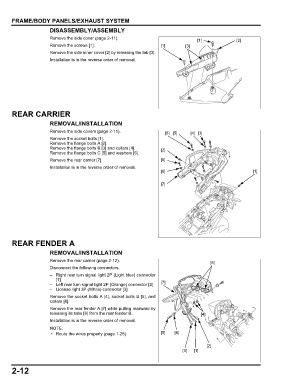
REAR CARRIER
REMOVAL/INSTALLATION
Remove the side covers (page 2-11). [6] [5] [4] [3]
Remove the socket bolts [1].
Remove the flange bolts A [2].
Remove the flange bolts B [3] and collars [4]. [2]
Remove the flange bolts C [5] and washers [6].
Remove the rear carrier [7]. [5]
Installation is in the reverse order of removal.
[6] [1]
[7]
REAR FENDER A
REMOVAL/INSTALLATION
Remove the rear carrier (page 2-12). [8]
Disconnect the following connectors.
– Right rear turn signal light 2P (Light blue) connector
[1]
– Left rear turn signal light 2P (Orange) connector [2] [7]
– License light 3P (White) connector [3]
Remove the socket bolts A [4], socket bolts B [5], and
collars [6].
Remove the rear fender A [7] while pulling rearward by
releasing its tabs [8] from the rear fender B. [4]
Installation is in the reverse order of removal.
• Route the wires properly (page 1-26). [5] [6]
[2]
[3] [1]
2-12