Page 91 - 2019 SHOP MANUAL CRF1000/A/D
P. 91

dummyheadmmyhead
             du

                                                                                                     MAINTENANCE
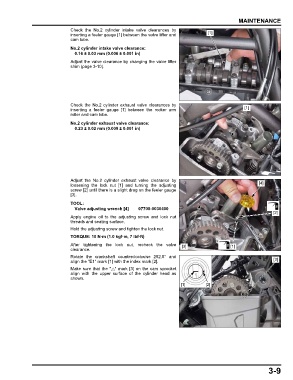
                               Check the No.2 cylinder intake valve clearances by
                               inserting a feeler gauge [1] between the valve lifter and  [1]
                               cam lobe.
                               No.2 cylinder intake valve clearance:
                                0.16 ± 0.03 mm (0.006 ± 0.001 in)
                               Adjust the valve clearance by changing the valve lifter
                               shim (page 3-10).


                               Check  the No.2  cylinder exhaust valve clearances by
                               inserting a feeler gauge [1] between the rocker arm                     [1]
                               roller and cam lobe.

                               No.2 cylinder exhaust valve clearance:
                                0.23 ± 0.02 mm (0.009 ± 0.001 in)


                               Adjust  the No.2 cylinder exhaust valve clearance  by
                               loosening the lock nut [1]  and  turning the adjusting                        [4]
                               screw [2] until there is a slight drag on the feeler gauge
                               [3].
                               TOOL:
                                Valve adjusting wrench [4]  07708-0030400
                                                                                                                   [2]
                               Apply engine oil to the adjusting screw and lock  nut
                               threads and seating surface.
                               Hold the adjusting screw and tighten the lock nut.
                               TORQUE: 10 N·m (1.0 kgf·m, 7 lbf·ft)
                               After tightening  the lock  nut, recheck the valve  [3]           [1]
                               clearance.
                               Rotate the crankshaft counterclockwise  252.5° and
                               align the "E1" mark [1] with the index mark [2].                                    [3]
                               Make sure that the " " mark [3] on the cam sprocket
                               align with the upper surface of  the cylinder head as
                               shown.
                                                                             [1]       [2]


                                                                                                                 3-9
   86   87   88   89   90   91   92   93   94   95   96