
Page 92 - 2019 SHOP MANUAL CRF1000/A/D
P. 92
du
dummyheadmmyhead
MAINTENANCE
Check the No.1 cylinder exhaust valve clearances by
inserting a feeler gauge [1] between the locker arm
roller and cam lobe.
[1]
No.1 cylinder exhaust valve clearance:
0.23 ± 0.02 mm (0.009 ± 0.001 in)
Adjust the No.1 cylinder exhaust valve clearance by
loosening the lock nut [1] and turning the adjusting [4] [3]
screw [2] until there is a slight drag on the feeler gauge
[3].
TOOL:
Valve adjusting wrench [4] 07708-0030400
[2]
Apply engine oil to the adjusting screw and lock nut
threads and seating surface.
Hold the adjusting screw and tighten the lock nut.
TORQUE: 10 N·m (1.0 kgf·m, 7 lbf·ft)
After tightening the lock nut, recheck the valve [1]
clearance.
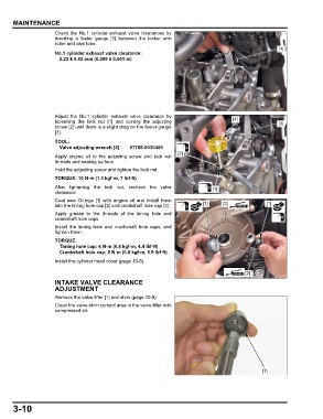
Coat new O-rings [1] with engine oil and install them
into the timing hole cap [2] and crankshaft hole cap [3]. [1] [3] [1]
Apply grease to the threads of the timing hole and
crankshaft hole caps.
Install the timing hole and crankshaft hole caps, and
tighten them.
TORQUE:
Timing hole cap: 6 N·m (0.6 kgf·m, 4.4 lbf·ft)
Crankshaft hole cap: 8 N·m (0.8 kgf·m, 5.9 lbf·ft)
Install the cylinder head cover (page 10-5).
[2]
INTAKE VALVE CLEARANCE
ADJUSTMENT
Remove the valve lifter [1] and shim (page 10-9).
Clean the valve shim contact area in the valve lifter with
compressed air.
[1]
3-10