Page 199 - 2019 SHOP MANUAL CRF1000/A/D
P. 199

dummyheadmmyhead
             du

                                                                                                 COOLING SYSTEM
                               Fill the system with the recommended coolant through
                               the filler opening up to filler neck [1].     [1]                  [2]
                               Remove the  radiator reserve  tank cap [2] and fill the
                               reserve tank to the upper level line.
                               Bleed air from the system as follows:
                               1. Shift the transmission into neutral.
                                 Start the engine and let it idle for 2 – 3 minutes.
                               2. Snap the throttle 3 or 4 times to bleed air from the
                                 system.
                               3. Stop the engine and add coolant up to the filler neck
                                 if necessary.
                               4. Install the radiator cap.
                               5. Check the level of coolant in the reserve tank and fill
                                 to the upper level line if it is low (page 3-14).


                                • When air bleeding is insufficient, level of coolant in
                                 the reserve tank will decrease. If so, fill to the upper
                                 level line with coolant.
                               After installation, check that there are no coolant leaks.
                               Install the removed parts in the  reverse order of
                               removal.


               THERMOSTAT

                               REMOVAL/INSTALLATION
                               Drain the coolant (page 8-4).
                                                                                                      [2]
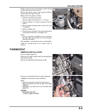
                               Disconnect the upper radiator hose [1] by loosening the
                               hose band screw [2].
                               Remove the bolts [3] and thermostat cover [4].  [1]


                                                                                                                   [3]

                                                                             [4]


                               Remove the thermostat [1] from the upper crankcase.
                                                                                                [2]
                               Installation is in the reverse order of removal.


                                • Install the thermostat air bleed hole [2] facing up.
                                • Align the thermostat ribs with the slits of the upper
                                 crankcase.
                                • Tighten the hose band screw to the specified range
                                 (page 8-8).
                               TORQUE:
                                Thermostat cover bolt:
                                  12 N·m (1.2 kgf·m, 9 lbf·ft)
                                                                                          [1]            Align


                                                                                                                 8-5
   194   195   196   197   198   199   200   201   202   203   204