Page 401 - 2019 SHOP MANUAL CRF1000/A/D
P. 401

dummyheadmmyhead
             du

                                                                              ENGINE REMOVAL/INSTALLATION
               ENGINE REMOVAL

                               Support the motorcycle using a safety stand or hoist.
                               Remove the following:
                               – Muffler/exhaust pipe (page 2-16)
                               – Engine oil filter (page 3-12)
                               – Ignition coil tray (page 5-9)
                               – Radiator (page 8-6)
                               – Radiator reserve tank (page 8-10)
                               – Gearshift spindle cover (CRF1000/A) (page 12-17)
                               – Shift pedal (CRF1000/A) (page 12-21)
                               – Rear brake pedal (page 19-15)
                               – Battery box (page 21-6)
                               – EOP switch (CRF1000/A) (page 22-19)
                               – EOP sensor (CRF1000D) (page 22-20)
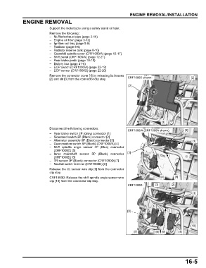
                               Remove the connector cover [1] by releasing its bosses
                               [2] and slit [3] from the connector clip stay.  CRF1000D shown:                     [2]

                                                                             [3]


                                                                                                 [1]

                               Disconnect the following connectors:
                                                                             CRF1000/A (CRF1000A shown):       [2]
                               – Rear brake switch 2P (Gray) connector [1]
                               – Sidestand switch 2P (Black) connector [2]
                               – Alternator assembly 6P (Black) connector [3]                                      [1]
                               – Gear position switch 8P (Black) (CRF1000/A) [4]
                               – Shift spindle angle sensor 3P (Blue) connector
                                 (CRF1000D) [5]
                               – Inner mainshaft sensor 3P (Black) connector  [3]
                                 (CRF1000D) [6]
                               – TR sensor 3P (Black) connector (CRF1000D) [7]
                               – Neutral switch terminal (CRF1000D) [8]
                               Release the O2 sensor wire clip [9] from the connector
                               clip stay.
                               CRF1000D: Release the shift spindle angle sensor wire             [4]     [9]
                               clip [10] from the connector clip stay.
                                                                             CRF1000D:       [3]       [2]

                                                                                                                    [1]


                                                                             [8]


                                                                                                                  [10]
                                                                                 [7]          [6]  [9]     [5]


                                                                                                               16-5
   396   397   398   399   400   401   402   403   404   405   406