
Page 406 - 2019 SHOP MANUAL CRF1000/A/D
P. 406
du
dummyheadmmyhead
ENGINE REMOVAL/INSTALLATION
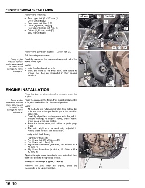
Remove the following:
Left side: [1] Right side: [6]
– Rear upper bolt (8 x 217 mm) [1]
– Collar (left side) [2] [5]
– Rear upper nut (8 mm) [3]
– Collar (right side, long) [4]
– Rear upper bolts (8 x 25 mm) [5] [7]
– Collars (right side, short) [6]
– Stay (right side) [7]
[2] [6] [3] [4]
Remove the swingarm pivot nut [1], pivot bolt [2].
Pull the swingarm rearward.
During engine Carefully maneuver the engine and remove it out of the
removal, hold the frame to the right.
engine securely and
be careful not to
damage the frame • Note the direction of the bolts.
and engine. • Mark and store all the bolts, nuts, and collars to
ensure that they are reinstalled in their original
locations.
[1]/[2]
ENGINE INSTALLATION
Place the jack or other adjustable support under the
engine.
During engine Place the engine in the frame, then loosely install all the
installation, hold the bolts, nuts and collars into the correct position.
engine securely and
be careful not to
damage the frame • All the bolts and nuts loosely install, then tighten the
and engine. bolts and nuts to the specified torque in the specified
sequence.
• Carefully align the mounting points with the jack to
prevent damage to engine, frame, water hoses,
brake pipes, wires, and cables.
• Route the hoses, wires, and cables properly (page
1-26)
• The jack height must be continually adjusted to
relieve stress for ease bolt installation.
Loosely install the following.
[3] [2]
– Right lower frame [1]
– Front lower bolt (10 x 138 mm) [2]
– Front lower nut (10 mm) [3]
– Right lower frame bolts (rear side, 10 x 60 mm, 10 x
75 mm) [4] [5]
– Right lower frame bolts (front side, 10 x 20 mm, 10 x
40 mm) [5]
Tighten the right lower frame bolts (rear side) first, then
front side bolts to the specified torque.
TORQUE: 44 N·m (4.5 kgf·m, 32 lbf·ft)
Remove the jack under the engine, place the [4] [1]
motorcycle in an upright position.
16-10