
Page 411 - 2019 SHOP MANUAL CRF1000/A/D
P. 411
dummyheadmmyhead
du
ENGINE REMOVAL/INSTALLATION
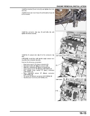
Install the bracket [1] and bolts [2], and tighten the bolts
securely. [1] [3] [4]
Install the fuel tank drain hose [3] and breather hose [4]
to the bracket.
[2]
Install the connector clip stay [1] and bolts [2], and
tighten the bolts securely. [1]
[2]
Install the O2 sensor wire clip [1] to the connector clip [4]
stay. CRF1000/A (CRF1000A shown):
CRF1000D: Install the shift spindle angle sensor wire
clip [2] to the connector clip stay. [3]
Connect the following connectors:
– Rear brake switch 2P (Gray) connector [3]
– Sidestand switch 2P (Black) connector [4] [5]
– Alternator assembly 6P (Black) connector [5]
– Gear position switch 8P (Black) (CRF1000/A) [6]
– Shift spindle angle sensor 3P (Blue) connector
(CRF1000D) [7]
– Inner mainshaft sensor 3P (Black) connector
(CRF1000D) [8]
– TR sensor 3P (Black) connector (CRF1000D) [9] [6] [1]
– Neutral switch terminal (CRF1000D) [10]
CRF1000D: [5] [4]
[3]
[10]
[2]
[9] [8] [1] [7]
16-15