Page 179 - 2019 SHOP MANUAL CRF1000/A/D
P. 179

dummyheadmmyhead
             du

                                                                                                      FUEL SYSTEM
                               Installation is in the reverse order of removal.


                                • A pressure release can be heard when opening the
                                 fuel cap, but this is not blockage of the passage. If
                                 checking for clog in the passage of the fuel tank side
                                 is necessary, apply air pressure to the breather hose
                                 end with the fuel filler cap opened.
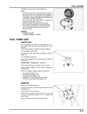
                                • If the fuel filler cap was  removed,  replace the
                                 breather seal [1] with a new one.
                                • Route the hoses, wires and harness properly.
                                • Be careful not to damage the harness and hose.
                                • After installing the fuel tank, make sure the drain,
                                 air vent, overflow hose and fuel hoses are not
                                 kinked or bound.                                                [1]

                               TORQUE:
                                Fuel filler cap bolt:
                                  1.8 N·m (0.2 kgf·m, 1.3 lbf·ft)


               FUEL PUMP UNIT

                               INSPECTION
                               Turn the ignition switch ON and engine stop switch " "
                               and confirm  that the  fuel  pump  operates for a few
                               seconds.
                               If the fuel pump does not operate, inspect as follows:
                               Turn the ignition switch OFF.
                                                                             [1]
                               Disconnect the fuel pump unit 3P (Black) connector
                               (page 7-4).
                               Turn the ignition switch ON.
                               Measure the voltage at the wire harness side 3P (Black)
                               connector [1].                                             Y/R       G
                               CONNECTION: Yellow/red (+) – Green (–)
                               There should be battery voltage for a few seconds.
                               If there is battery voltage for a few seconds, replace the
                               fuel pump unit.
                               If there is no battery voltage, inspect the following:
                               – Sub fuse ENG STOP 7.5 A
                               – Fuel pump relay (page 7-10)
                               – Fuel pump relay related circuit
                               – Open circuit in the Yellow/red or Green wire
                               – ECM/PCM power/ground line (page 4-40)

                               REMOVAL

                               Remove the fuel tank (page 7-6).
                                                                             [3]                     [1]
                               Disconnect the quick connect fitting from the fuel pump
                               unit (page 7-4).
                               Clean around the fuel pump unit.
                               Loosen the fuel pump unit mounting nuts [1] and cap
                               nut  [2] in a  crisscross  pattern in 2 or 3 steps  and
                               remove them.
                               Remove the fuel pump unit [3] and packing [4].


                                                                                                     [2]      [4]


                                                                                                                 7-7
   174   175   176   177   178   179   180   181   182   183   184