Page 423 - 2019 SHOP MANUAL CRF1000/A/D
P. 423

dummyheadmmyhead
             du

                                                                       FRONT WHEEL/SUSPENSION/STEERING
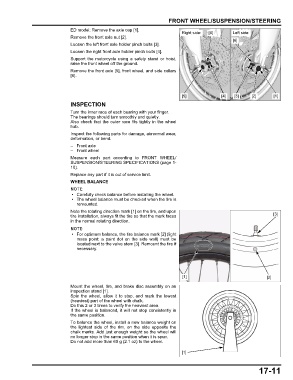
                               ED model: Remove the axle cap [1].
                                                                             Right side:  [6]     Left side:
                               Remove the front axle nut [2].
                                                                                                  [6]
                               Loosen the left front axle holder pinch bolts [3].
                               Loosen the right front axle holder pinch bolts [4].
                               Support the  motorcycle using a safety stand or  hoist,
                               raise the front wheel off the ground.
                               Remove the front axle [5], front wheel, and side collars
                               [6].


                                                                             [5]              [4]  [3]    [2]      [1]
                               INSPECTION

                               Turn the inner race of each bearing with your finger.
                               The bearings should turn smoothly and quietly.
                               Also check that the outer race fits tightly in the wheel
                               hub.
                               Inspect the following parts for damage, abnormal wear,
                               deformation, or bend.
                               –Front axle
                               – Front wheel
                               Measure each part according to FRONT WHEEL/
                               SUSPENSION/STEERING SPECIFICATIONS (page 1-
                               10).
                               Replace any part if it is out of service limit.
                               WHEEL BALANCE

                                • Carefully check balance before installing the wheel.
                                • The wheel balance must be checked when the tire is
                                 remounted.
                               Note the rotating direction mark [1] on the tire, and upon
                               tire installation, always fit the tire so that the mark faces                       [3]
                               in the normal rotating direction.

                                • For optimum balance, the tire balance mark [2] (light
                                 mass point: a  paint  dot  on the side  wall) must  be
                                 located next to the valve stem [3]. Remount the tire if
                                 necessary.


                                                                             [1]                                [2]
                               Mount the wheel, tire, and brake disc assembly on an
                               inspection stand [1].
                               Spin the  wheel, allow it to  stop, and  mark the lowest
                               (heaviest) part of the wheel with chalk.
                               Do this 2 or 3 times to verify the heaviest area.
                               If the wheel is balanced, it will not stop consistently in
                               the same position.
                               To balance the wheel, install a new balance weight on
                               the  lightest  side of  the rim, on the side opposite the
                               chalk marks. Add just enough weight so the wheel will
                               no longer stop in the same position when it is spun.
                               Do not add more than 60 g (2.1 oz) to the wheel.

                                                                             [1]


                                                                                                             17-11
   418   419   420   421   422   423   424   425   426   427   428