
Page 493 - 2019 SHOP MANUAL CRF1000/A/D
P. 493
dummyheadmmyhead
du
ANTI-LOCK BRAKE SYSTEM (ABS) (CRF1000A/D)
How to erase the DTC without MCS
1. Connect the SCS connector to the DLC (page 4-6).
2. Turn the ignition switch ON and engine stop switch " " while squeezing either brake lever. The ABS indicator should come on
for 2 seconds and go off.
3. Release the brake lever immediately after the ABS indicator goes off. The ABS indicator should come on.
4. Squeeze the brake lever immediately after the ABS indicator comes on. The ABS indicator should go off.
5. Release the brake lever immediately after the ABS indicator goes off.
When the DTC is erased, the ABS indicator blinks 2 times and stays on.
If the ABS indicator does not blink 2 times, the self-diagnostic memory has not been erased, so try again.
6. Turn the ignition switch OFF and disconnect the SCS connector.
Install the removed parts in the reverse order of removal.
CIRCUIT INSPECTION
INSPECTION AT ABS MODULATOR CONNECTOR
Remove the ETC tray (page 2-11).
Disconnect: Connect:
Turn the ignition switch OFF.
[1] [2]
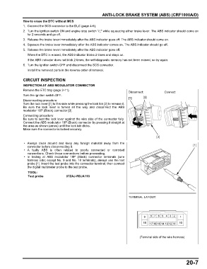
Disconnecting procedure:
Turn the lock lever [1] to this side while pressing the lock tab [2] to release it.
Be sure the lock lever is turned all the way and disconnect the ABS
modulator 18P (Black) connector [3].
Connecting procedure:
Be sure to seat the lock lever against the wire side of the connector fully.
Connect the ABS modulator 18P (Black) connector by pressing it straight at
the area as shown (arrow) until the lock tab clicks.
Make sure the connector is locked securely.
[3]
• Always clean around and keep any foreign material away from the
connector before disconnecting it. [1]
• A faulty ABS is often related to poorly connected or corroded
connections. Check those connections before proceeding.
• In testing at ABS modulator 18P (Black) connector terminals (wire
harness side; except No. 9 and No. 18 terminals), always use the test
probe [1]. Insert the test probe into the connector terminal, then connect
the digital multimeter probe to the test probe.
TOOL:
Test probe 07ZAJ-RDJA110
TERMINAL LAYOUT:
(Terminal side of the wire harness)
20-7