
Page 496 - 2019 SHOP MANUAL CRF1000/A/D
P. 496
du
dummyheadmmyhead
ANTI-LOCK BRAKE SYSTEM (ABS) (CRF1000A/D)
ABS INDICATOR CIRCUIT
TROUBLESHOOTING
ABS INDICATOR DOES NOT COME ON
(when the ignition switch turned ON)
• Before starting this inspection, check the initial
function of the combination meter (page 22-12).
1. Indicator Operation Inspection
Turn the ignition switch OFF.
Disconnect the ABS modulator 18P (Black)
connector (page 20-7).
Turn the ignition switch ON and engine stop switch
"".
Check the ABS indicator.
Does the ABS indicator come on?
YES – Faulty ABS modulator
NO – GO TO STEP 2.
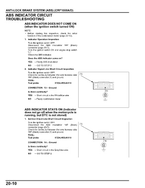
2. Indicator Signal Line Short Circuit Inspection
Turn the ignition switch OFF.
Check for continuity between the wire harness side [1]
18P (Black) connector [1] and ground.
TOOL:
Test probe 07ZAJ-RDJA110
CONNECTION: 13 – Ground
Is there continuity? 13
YES – Short circuit in the White/blue wire
NO – Faulty combination meter
ABS INDICATOR STAYS ON (Indicator
does not go off when the motorcycle is
running, but DTC is not stored)
1. Service Check Line Short Circuit Inspection
Turn the ignition switch OFF.
Disconnect the ABS modulator 18P (Black) [1]
connector (page 20-7).
Check for continuity between the wire harness side
18P (Black) connector [1] and ground.
TOOL:
Test probe 07ZAJ-RDJA110
14
CONNECTION: 14 – Ground
Is there continuity?
YES – Short circuit in the Gray/blue wire
NO – GO TO STEP 2.
20-10