
Page 500 - 2019 SHOP MANUAL CRF1000/A/D
P. 500
du
dummyheadmmyhead
ANTI-LOCK BRAKE SYSTEM (ABS) (CRF1000A/D)
DTC 1-3, 1-4, 2-3, or 4-3 (Rear Wheel
Speed Sensor Circuit/Rear Wheel
Speed Sensor/Rear Pulser Ring/Rear
Wheel Lock)
• The ABS indicator might blink under unusual riding
conditions (page 20-8). This is temporary failure.
Erase the DTC (page 20-6).
Then test-ride the motorcycle above 10 km/h (6
mph) to check that the ABS indicator operates
normally (page 20-5).
• If DTC 4-3 is indicated, check the rear brake for
drag.
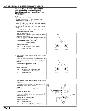
1. Rear Wheel Speed Sensor Line Short Circuit
Inspection (at sensor side)
Turn the ignition switch OFF.
Disconnect the rear wheel speed sensor 2P (Black) [1]
connector (page 20-22).
Check for continuity between each terminal of the
sensor side 2P (Black) connector [1] and ground.
CONNECTION: White – Ground W Bu
Blue – Ground
Is there continuity?
YES – Faulty rear wheel speed sensor
NO – GO TO STEP 2.
2. Rear Wheel Speed Sensor Line Short Circuit
Inspection
Check for continuity between each terminal of the [1]
wire harness side 2P (Black) connector [1] and
ground.
CONNECTION: White – Ground
Blue – Ground Bu W
Is there continuity?
YES – • Short circuit in the White wire
• Short circuit in the Blue wire
NO – GO TO STEP 3.
3. Rear Wheel Speed Sensor Line Open Circuit
Inspection
Short the wire harness side 18P (Black) connector
[1] terminals with a jumper wire [2]. [2] [1]
TOOL: 6
Test probe 07ZAJ-RDJA110
CONNECTION: 6 – 15
Check for continuity at the wire harness side 2P 15 [3]
(Black) connector [3].
CONNECTION: Blue – White
Bu W
Is there continuity?
YES – GO TO STEP 4.
NO – Open circuit in the Blue or White wire
20-14