
Page 503 - 2019 SHOP MANUAL CRF1000/A/D
P. 503
dummyheadmmyhead
du
ANTI-LOCK BRAKE SYSTEM (ABS) (CRF1000A/D)
DTC 5-1 or 5-4 (Pump Motor Lock/
Power Supply Relay)
1. Fuse Inspection
Turn the ignition switch OFF.
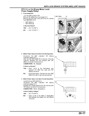
Remove the battery box cover (page 6-7). CRF1000A: [1]
Remove the fuse case cover and check for a blown
fuse ABS MAIN 30 A.
– CRF1000A [1]
– CRF1000D [2]
Is the fuse blown?
YES – GO TO STEP 2.
NO – GO TO STEP 3.
CRF1000D: [2]
2. Motor Power Input Line Short Circuit Inspection
Disconnect the ABS modulator 18P (Black)
connector (page 20-7). [1]
With the fuse ABS MAIN 30 A removed, check for
continuity between the wire harness side 18P
(Black) connector [1] and ground.
CONNECTION: 18 – Ground
Is there continuity?
18
YES – Short circuit in the Red/yellow wire
between the ABS fuse case and 18P
(Black) connector
NO – Intermittent failure. Replace the fuse ABS
MAIN 30 A with a new one and recheck.
3. Motor Power Input Line Open Circuit Inspection
Install the fuse ABS MAIN 30 A.
Disconnect the ABS modulator 18P (Black) [1]
connector (page 20-7).
Measure the voltage between the wire harness side
18P (Black) connector [1] and ground.
CONNECTION: 18 (+) – Ground (–)
Is there battery voltage?
18
YES – GO TO STEP 4.
NO – Open circuit in the Black or Red/yellow
wire between the battery and 18P (Black)
connector
20-17