
Page 506 - 2019 SHOP MANUAL CRF1000/A/D
P. 506
dummyheadmmyhead
du
ANTI-LOCK BRAKE SYSTEM (ABS) (CRF1000A/D)
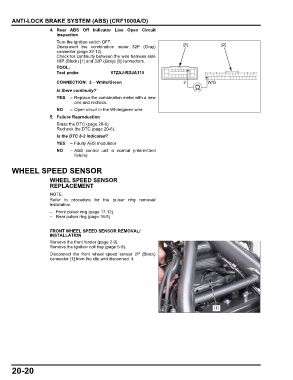
4. Rear ABS Off Indicator Line Open Circuit
Inspection
Turn the ignition switch OFF.
Disconnect the combination meter 32P (Gray) [1] [2]
connector (page 22-12).
Check tor continuity between the wire harness side
18P (Black) [1] and 32P (Gray) [2] connectors.
TOOL:
Test probe 07ZAJ-RDJA110
CONNECTION: 2 – White/Green 2 W/G
Is there continuity?
YES – Replace the combination meter with a new
one and recheck.
NO – Open circuit in the White/green wire
5. Failure Reproduction
Erase the DTC (page 20-6).
Recheck the DTC (page 20-6).
Is the DTC 8-2 indicated?
YES – Faulty ABS modulator
NO – ABS control unit is normal (intermittent
failure)
WHEEL SPEED SENSOR
WHEEL SPEED SENSOR
REPLACEMENT
Refer to procedure for the pulser ring removal/
installation.
– Front pulser ring (page 17-12)
– Rear pulser ring (page 18-5)
FRONT WHEEL SPEED SENSOR REMOVAL/
INSTALLATION
Remove the front fender (page 2-9).
Remove the ignition coil tray (page 5-9).
Disconnect the front wheel speed sensor 2P (Black)
connector [1] from the clip and disconnect it.
[1]
20-20