Page 501 - 2019 SHOP MANUAL CRF1000/A/D
P. 501

dummyheadmmyhead
             du

                                                              ANTI-LOCK BRAKE SYSTEM (ABS) (CRF1000A/D)
                               4. Failure Reproduction with a New Speed Sensor
                                 Replace the rear wheel speed  sensor with a new
                                 one (page 20-22).
                                 Connect the 18P (Black) and 2P (Black) connectors.
                                 Erase the DTC (page 20-6).
                                 Test-ride the motorcycle above 10 km/h (6 mph).
                                 Recheck the DTC (page 20-6).
                                 Is the DTC 1-3, 1-4, 2-3, or 4-3 indicated?
                                 YES   – Faulty ABS modulator
                                 NO    – Faulty original rear wheel speed sensor

                               DTC 1-5 (Front or Rear Wheel Speed
                               Sensor Circuit: Short)
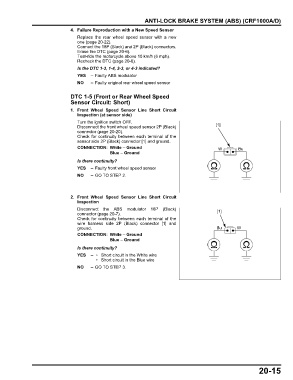
                               1. Front Wheel Speed  Sensor Line Short  Circuit
                                 Inspection (at sensor side)
                                 Turn the ignition switch OFF.
                                 Disconnect the front wheel speed sensor 2P (Black)        [1]
                                 connector (page 20-20).
                                 Check for continuity between each terminal of the
                                 sensor side 2P (Black) connector [1] and ground.
                                 CONNECTION: White – Ground                                 W        Bu
                                               Blue – Ground
                                 Is there continuity?
                                 YES   – Faulty front wheel speed sensor
                                 NO    – GO TO STEP 2.


                               2. Front Wheel Speed  Sensor Line Short  Circuit
                                 Inspection
                                 Disconnect the ABS  modulator 18P (Black)                  [1]
                                 connector (page 20-7).
                                 Check for continuity between each terminal of the
                                 wire harness side 2P (Black) connector [1] and
                                 ground.                                                    Bu      W
                                 CONNECTION: White – Ground
                                               Blue – Ground
                                 Is there continuity?
                                 YES   –  • Short circuit in the White wire
                                          • Short circuit in the Blue wire
                                 NO    – GO TO STEP 3.


                                                                                                             20-15
   496   497   498   499   500   501   502   503   504   505   506