
Page 498 - 2019 SHOP MANUAL CRF1000/A/D
P. 498
dummyheadmmyhead
du
ANTI-LOCK BRAKE SYSTEM (ABS) (CRF1000A/D)
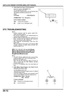
6. Power Input Line Open Circuit Inspection
Install the sub fuse ABS MAIN 7.5 A.
Turn the ignition switch ON. [1]
Measure the voltage between the wire harness side
18P (Black) connector [1] and ground.
TOOL:
Test probe 07ZAJ-RDJA110
CONNECTION: 7 (+) – Ground (–) 7
Is there battery voltage?
YES – Faulty ABS modulator
NO – Open circuit in Red/green wire
DTC TROUBLESHOOTING
• Perform inspection with the ignition switch OFF,
unless otherwise specified.
• All connector diagrams in the troubleshooting are
viewed from the terminal side.
• When the ABS modulator assembly is detected to be
faulty, recheck the wire harness and connector
connections closely before replacing it.
• After diagnostic troubleshooting, erase the DTC
(page 20-6).
Then test-ride the motorcycle to check that the ABS
indicator operates normally during pre-start self-
diagnosis (page 20-5).
DTC 1-1, 1-2, 2-1, 4-1 or 4-2 (Front
Wheel Speed Sensor Circuit/Front
Wheel Speed Sensor/Front Pulser
Ring/Front Wheel Lock)
• The ABS indicator might blink under unusual riding
conditions (page 20-8). This is temporary failure.
Erase the DTC (page 20-6).
Then test-ride the motorcycle above 10 km/h (6
mph) to check that the ABS indicator operates
normally (page 20-5).
• If DTC 4-1 is indicated, check the front brake for
drag.
1. Front Wheel Speed Sensor Line Short Circuit
Inspection (at sensor side)
Turn the ignition switch OFF.
Disconnect the front wheel speed sensor 2P (Black) [1]
connector (page 20-20).
Check for continuity between each terminal of the
sensor side 2P (Black) connector [1] and ground.
CONNECTION: White – Ground W Bu
Blue – Ground
Is there continuity?
YES – Faulty front wheel speed sensor
NO – GO TO STEP 2.
20-12