
Page 494 - 2019 SHOP MANUAL CRF1000/A/D
P. 494
dummyheadmmyhead
du
ANTI-LOCK BRAKE SYSTEM (ABS) (CRF1000A/D)
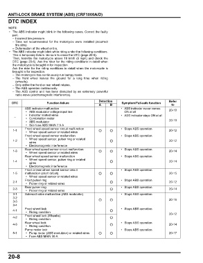
DTC INDEX
• The ABS indicator might blink in the following cases. Correct the faulty
part.
– Incorrect tire pressure.
– Tires not recommended for the motorcycle were installed (incorrect
tire size).
– Deformation of the wheel or tire.
• The ABS indicator might blink while riding under the following conditions.
This is temporary failure. Be sure to erase the DTC (page 20-6).
Then, test-ride the motorcycle above 10 km/h (6 mph) and check the
DTC (page 20-6). Ask the rider for the riding conditions in detail when
the motorcycle is brought in for inspection.
Ask the rider for the riding conditions in detail when the motorcycle is
brought in for inspection.
– The motorcycle has continuously run bumpy roads.
– The front wheel leaves the ground for a long time when riding
(wheelie).
– Only either the front or rear wheel rotates.
– The ABS operates continuously.
– The ABS control unit has been disrupted by an extremely powerful
radio wave (electromagnetic interference).
Detection Refer
DTC Function failure Symptom/Fail-safe function
A B to
ABS indicator malfunction • ABS indicator never comes 20-10
• ABS modulator voltage input line ON at all
• Indicator related wires • ABS indicator stays ON at all
–
• Combination meter 20-10
• ABS modulator
• Sub fuse ABS MAIN 7.5 A
Front wheel speed sensor circuit malfunction • Stops ABS operation
1-1 20-12
• Wheel speed sensor or related wires
Front wheel speed sensor malfunction • Stops ABS operation
• Wheel speed sensor, pulser ring or related
1-2 20-12
wires
• Electromagnetic interference
Rear wheel speed sensor circuit malfunction • Stops ABS operation
1-3 20-14
• Wheel speed sensor or related wires
Rear wheel speed sensor malfunction • Stops ABS operation
• Wheel speed sensor, pulser ring or related
1-4 20-14
wires
• Electromagnetic interference
Front or rear wheel speed sensor circuit • Stops ABS operation
1-5 malfunction (short circuit) 20-15
• Wheel speed sensor or related wires
Front pulser ring • Stops ABS operation
2-1 20-12
• Pulser ring or related wires
Rear pulser ring • Stops ABS operation
2-3 20-14
• Pulser ring or related wires
3-1 Solenoid valve malfunction (ABS modulator) • Stops ABS operation
3-2 20-16
3-3
3-4
Front wheel lock • Stops ABS operation
4-1
• Riding condition 20-12
Front wheel lock (Wheelie)
4-2
• Riding condition
Rear wheel lock • Stops ABS operation
4-3 20-14
• Riding condition
Pump motor lock • Stops ABS operation
5-1 • Pump motor (ABS modulator) or related wires 20-17
• Fuse ABS MAIN 30 A
20-8