
Page 302 - 2019 SHOP MANUAL CRF1000/A/D
P. 302
du
dummyheadmmyhead
DUAL CLUTCH TRANSMISSION (DCT) (CRF1000D)
5. Clutch EOP Sensor Output Line Short Circuit
Inspection
Turn the ignition switch OFF.
Disconnect the PCM 33P (Blue) connector (page 4- [1]
39).
Check for continuity between the wire harness side
sensor 3P connector [1] and ground.
Connection:
No.1 clutch EOP sensor:
Yellow/green – Ground Y/G or Bl/G
No.2 clutch EOP sensor:
Black/green – Ground
Is there continuity?
YES – • Short circuit in the Yellow/green wire
• Short circuit in the Black/green wire
NO – Replace the PCM with a known good one
(page 4-39) and recheck.
DTC 47-2 or 48-2 (No.1 or No.2
CLUTCH EOP SENSOR HIGH
VOLTAGE)
• Before starting the inspection, check for loose or
poor contact on the clutch EOP sensor 3P (No.1:
Gray, No.2: Black), and PCM 33P (Blue) and 33P
(Black) connectors, and recheck the DTC.
1. Clutch EOP Sensor System Inspection
Check the clutch EOP sensor with the MCS.
Is about 5 V indicated?
YES – GO TO STEP 2.
NO – Intermittent failure
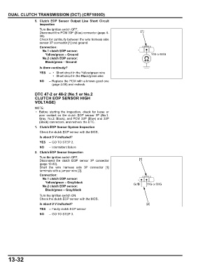
2. Clutch EOP Sensor Inspection
Turn the ignition switch OFF.
Disconnect the clutch EOP sensor 3P connector [1]
(page 13-80).
Short the wire harness side 3P connector [1]
terminals with a jumper wire [2].
Connection:
No.1 clutch EOP sensor:
Yellow/green – Gray/black
No.2 clutch EOP sensor: Gr/Bl Y/G or Bl/G
Black/green – Gray/black
Turn the ignition switch ON.
Check the clutch EOP sensor with the MCS.
Is about 0 V indicated? [2]
YES – Faulty clutch EOP sensor
NO – GO TO STEP 3.
13-32