Page 297 - 2019 SHOP MANUAL CRF1000/A/D
P. 297

dummyheadmmyhead
             du

                                                             DUAL CLUTCH TRANSMISSION (DCT) (CRF1000D)
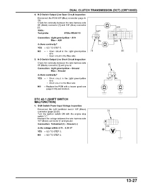
                               4. N-D Switch Output Line Open Circuit Inspection
                                 Disconnect the PCM 33P (Blue) connector (page 4-
                                 39).
                                 Check for continuity between the wire harness side
                                 6P (Black) connector [1] and 33P (Blue) connector
                                 [2].                                                                A19
                                 TOOL:                                              Lg/Y
                                 Test probe             07ZAJ-RDJA110

                                 Connection: Light green/yellow – A19
                                             Blue – A20                               Bu           A20
                                 Is there continuity?
                                 YES – GO TO STEP 5.
                                 NO    –  • Open circuit  in the Light  green/yellow  [1]                [2]
                                           wire
                                          • Open circuit in the Blue wire
                               5. N-D Switch Output Line Short Circuit Inspection
                                 Check for continuity between the wire harness side
                                 6P (Black) connector [1] and ground.                         [1]
                                 Connection: Light green/yellow – Ground
                                             Blue – Ground
                                 Is there continuity?
                                 YES –  • Short  circuit in the  Light green/yellow          Lg/Y  Bu
                                           wire
                                          • Short circuit in the Blue wire
                                 NO    – Replace the PCM with a known good one
                                         (page 4-39) and recheck.


                               DTC 42-1 (SHIFT SWITCH
                               MALFUNCTION)
                               1. Shift Switch Power Input Voltage Inspection
                                 Disconnect the Left  handlebar switch 12P (Black)
                                 connector (page 22-23).                                     [1]
                                 Turn the ignition switch  ON with the  engine stop
                                 switch " ".
                                 Measure the voltage between the wire harness side
                                 12P (Black) connector [1] and ground.
                                 Connection: Yellow/red (+) – Ground (–)
                                                                                            Y/R
                                 Is the voltage within 4.75 – 5.25 V?
                                 YES – GO TO STEP 3.
                                 NO    – GO TO STEP 2.


                                                                                                             13-27
   292   293   294   295   296   297   298   299   300   301   302