Page 293 - 2019 SHOP MANUAL CRF1000/A/D
P. 293

dummyheadmmyhead
             du

                                                             DUAL CLUTCH TRANSMISSION (DCT) (CRF1000D)
                               DTC 27-1 (SHIFT DRUM POSITION
                               MALFUNCTION)

                               1. TR Sensor System Inspection
                                 Check the TR sensor with the MCS.
                                 Is Low voltage (about 0 V) or High voltage (about
                                 5 V) indicated?
                                 YES   –  • About 0 V: See DTC 51-1 (page 13-34).
                                          • About 5 V: See DTC 51-2 (page 13-36).
                                 NO    – GO TO STEP 2.
                               2. Shift Control Motor/Reduction gear condition
                                 Check the shift control motor and reduction gears
                                 are  installed properly  and are not damaged  (page
                                 13-71).
                                 Are the shift control motor and reduction gears
                                 in normal condition?
                                 YES   – GO TO STEP 3.
                                 NO    – Install the shift control motor and reduction
                                         gears properly or replace faulty parts.
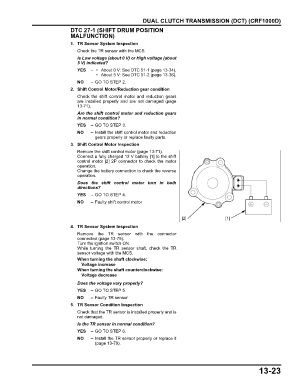
                               3. Shift Control Motor Inspection
                                 Remove the shift control motor (page 13-71).
                                 Connect a fully charged 12 V battery [1] to the shift
                                 control motor [2] 2P connector to check the motor
                                 operation.
                                 Change the battery connection to check the reverse
                                 operation.
                                 Does the  shift control motor turn in both
                                 directions?
                                 YES   – GO TO STEP 4.
                                 NO    – Faulty shift control motor


                                                                             [2]               [1]
                               4. TR Sensor System Inspection
                                 Remove  the TR sensor with the  connector
                                 connected (page 13-79).
                                 Turn the ignition switch ON.
                                 While turning the  TR sensor shaft, check the  TR
                                 sensor voltage with the MCS.
                                 When turning the shaft clockwise:
                                   Voltage increase
                                 When turning the shaft counterclockwise:
                                   Voltage decrease
                                 Does the voltage vary properly?
                                 YES   – GO TO STEP 5.
                                 NO    – Faulty TR sensor
                               5. TR Sensor Condition Inspection
                                 Check that the TR sensor is installed properly and is
                                 not damaged.
                                 Is the TR sensor in normal condition?
                                 YES   – GO TO STEP 6.
                                 NO    – Install the TR sensor properly or replace it
                                         (page 13-79).


                                                                                                             13-23
   288   289   290   291   292   293   294   295   296   297   298